
Improved device for cool drying

A technology of cold drying and equipment, which is applied to the separation of dispersed particles, chemical instruments and methods, separation methods, etc., can solve the problems of complexity, heavy cooling circuit manufacturing, time-consuming assembly, etc., and achieve multi-energy, simple and energy-saving. Effect

Active Publication Date: 2008-07-16
ATLAS COPCO AIRPOWER NV
View PDF2 Cites 4 Cited by
  • Summary
  • Abstract
  • Description
  • Claims
  • Application Information

AI Technical Summary

Problems solved by technology

[0013] A disadvantage of such known devices is that the cooling circuit has to be made heavy and large due to the presence of the aforementioned thermal mass
[0014] Another disadvantage of such known devices is that the construction of the cooling circuit is relatively expensive and complicated due to additional parts, such as containers and / or additional heat exchangers, and its assembly is time-consuming

Method used


Image

  • Improved device for cool drying
  • Improved device for cool drying
  • Improved device for cool drying

Examples


Embodiment Construction

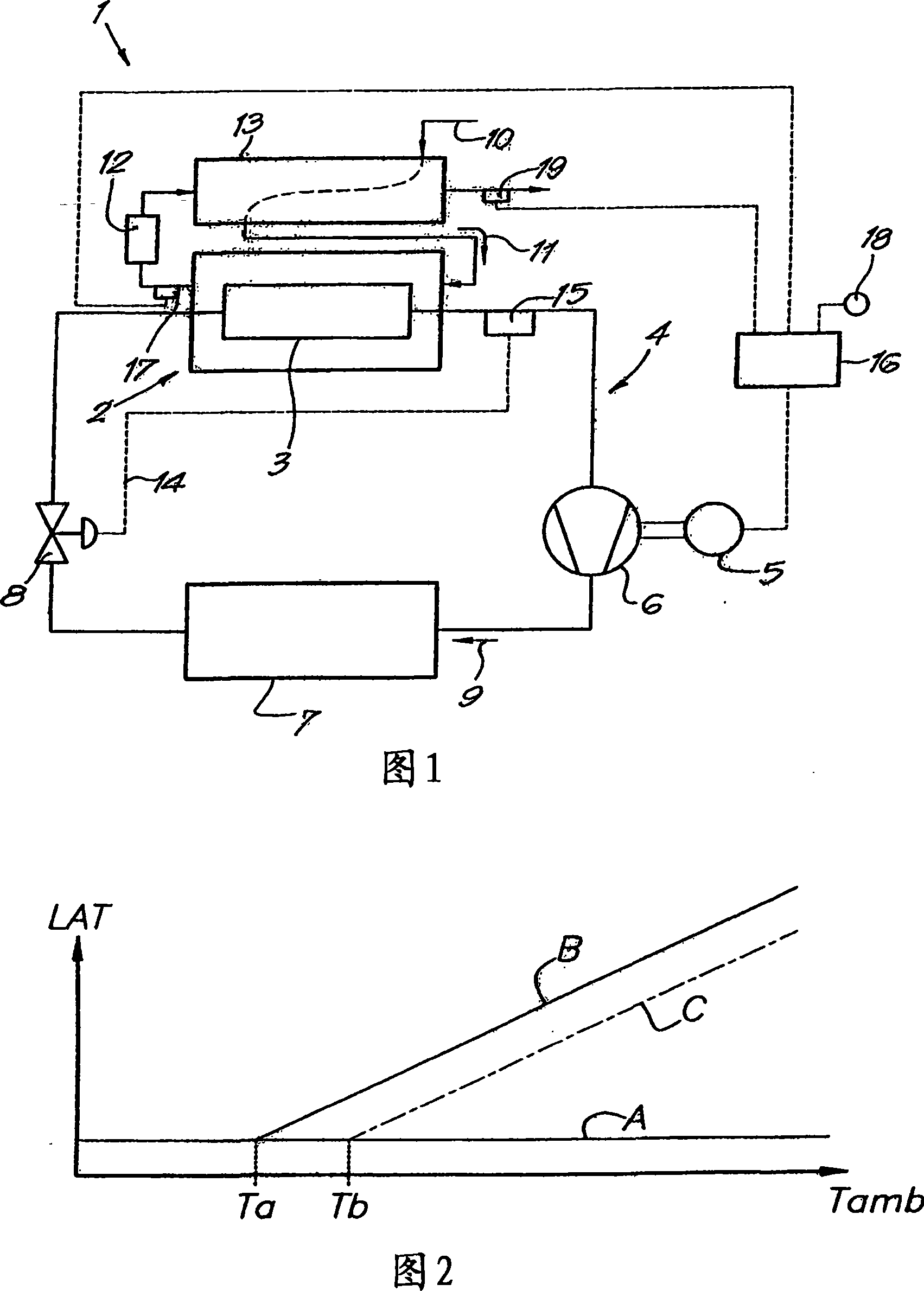
[0028] Figure 1 shows a device 1 for cold drying, which mainly consists of a heat exchanger 2, the first part of which forms an evaporator 3 of a cooling circuit 4, in which a motor driven by an electric motor 5 is also arranged in succession. Compressor 6, condenser 7 and expansion device 8.

[0029] The cooling circuit is filled with a cooling fluid, for example Freon R410a, the flow direction of which is indicated by arrow 9 .

[0030] The second part of the heat exchanger 2 is a part of the tube 10 for the moist air to be dried, the flow direction of which is indicated by the arrow 11 .

[0031] After the heat exchanger 2 , ie at its outlet, a liquid separator 12 is arranged in the tube 10 .

[0032] This pipe 10 may extend partly through a precooler or recuperator 13 before reaching the heat exchanger 2, and then, after the liquid separator 12, again through the recuperator 13, with the aforementioned part parallel or opposite flow.

[0033] The outlet of the above-men...


PUM


Abstract

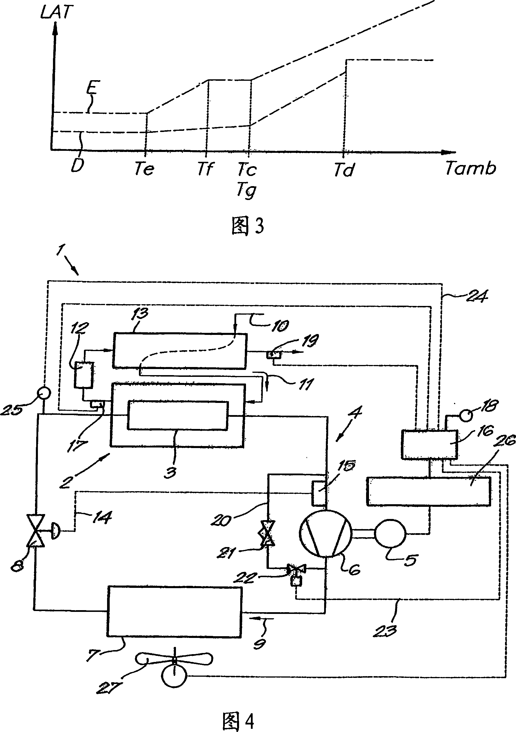
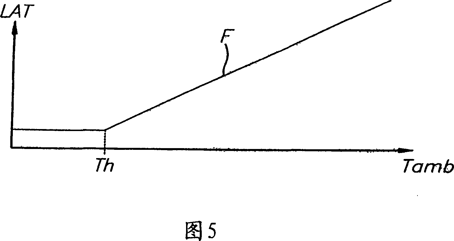
Device for cool drying comprising a heat exchanger (2) whose primary part is the vaporizer (3) of a cooling circuit (4) which also comprises a compressor (6) driven by a motor (5), a control device (16) for this motor (5) and measuring means (17) for the lowest air temperature (LAT) , measuring means (18) for the ambient temperature (Tamb) and a flow meter (19), whereby this control device (16) can be at least switched in a first user mode in which the cooling circuit (4) is only activated when the gas flow exceeds a preset value and a second user mode in which the lowest air temperature (LAT) is maintained within a certain range by controlling the cooling circuit (4) .

Description

technical field [0001] The present invention relates to an improved apparatus for cold drying. Background technique [0002] In particular, the invention relates to a plant for cold drying comprising a heat exchanger whose first part is the evaporator of a cooling circuit also comprising a compressor driven by an electric motor, a condenser , the expansion device between the outlet of the condenser and the inlet of the evaporator, the control device for controlling the above-mentioned motor and the measuring device coupled to it, while the second part of the heat exchanger is for the gas to be dried A part of the tube whereby the liquid separator is arranged at the outlet of the second part of the heat exchanger in the tube. [0003] Compressed air, for example supplied by a compressor, is in most cases filled with water vapour, or in other words has a relative humidity of 100%. This means that in case the temperature drops below the so-called dew point, there will be cond...

Claims


Application Information

Patent Timeline
Patent Type & Authority Applications(China)
IPC IPC(8): B01D53/26
CPCB01D53/265B01D53/26
Inventor M·达拉瓦莱W·D·A·范戴克
Owner ATLAS COPCO AIRPOWER NV
Learn More