Vehicle running control device for running extremely low speed to stop

A technology of vehicle driving and control devices, which is applied in the direction of engine control, machine/engine, mechanical equipment, etc., and can solve problems such as inapplicability

Inactive Publication Date: 2007-01-31
ADVICS CO LTD
View PDF1 Cites 4 Cited by
  • Summary
  • Abstract
  • Description
  • Claims
  • Application Information

AI Technical Summary

Problems solved by technology

[0004] However, the technology disclosed in Japanese Patent Application Laid-Open No. JP-A-2005-57962, in which a motor is used to run a vehicle at an extremely low speed, can only be applied to a vehicle equipped with a motor.
This technique cannot be applied to vehicles running solely on engine power, which are the most common types of vehicles in use

Method used


Image

  • Vehicle running control device for running extremely low speed to stop
  • Vehicle running control device for running extremely low speed to stop
  • Vehicle running control device for running extremely low speed to stop

Examples


no. 1 example

[0027] A parking assist control system equipped with a vehicle travel control device to which a first embodiment of the present invention is applied will now be described with reference to the drawings.

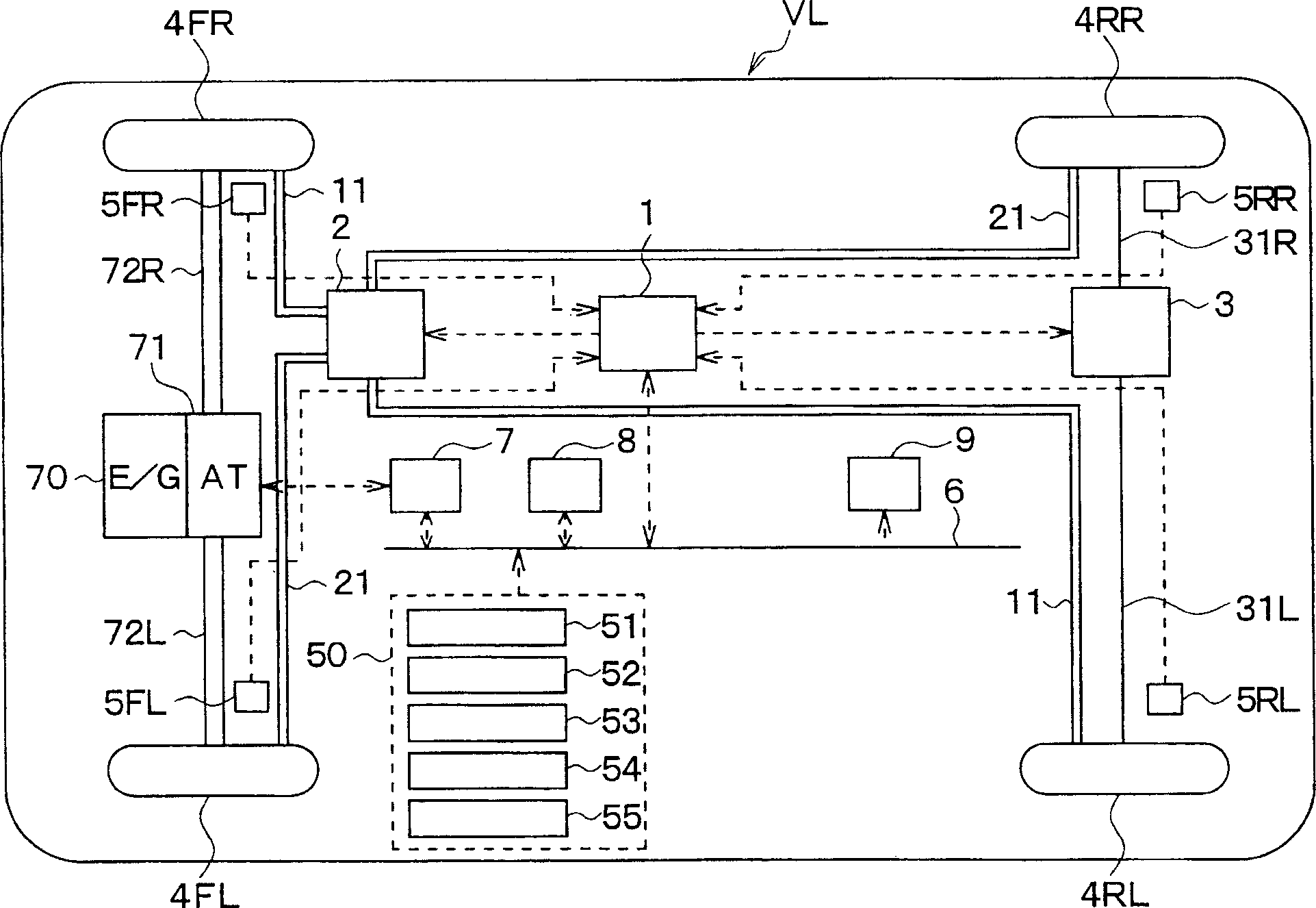
[0028] figure 1 is a diagram showing the overall configuration of the parking assist control system of this embodiment. In this figure, a vehicle VL has a front left wheel, a front right wheel, a rear left wheel and a right rear wheel, and their corresponding structural components are designated and indicated by FL, FR, RL and RR, respectively.

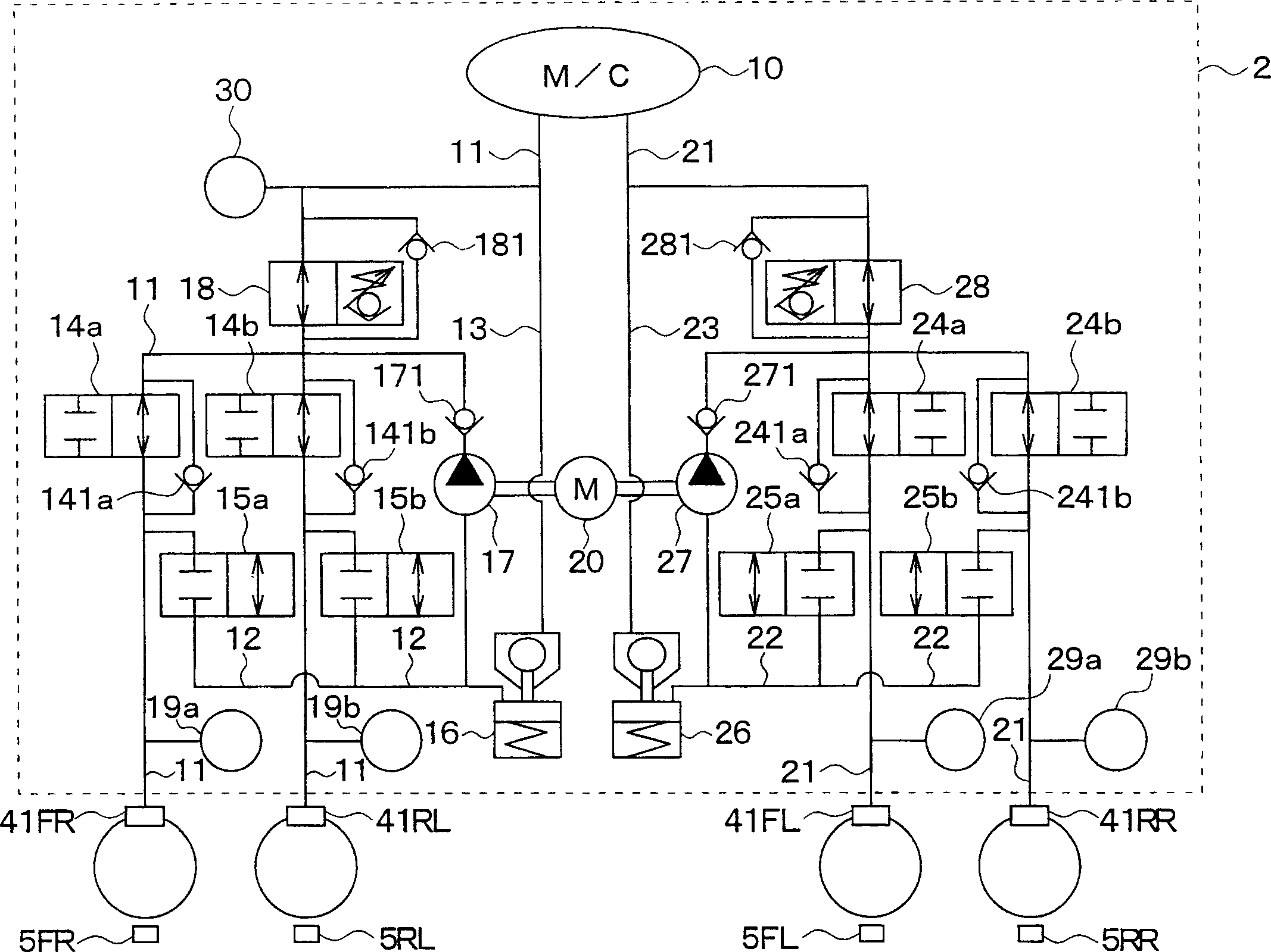
[0029] The parking assist control system of the present embodiment has a configuration including a brake control ECU 1; a hydraulic brake device 2; an electric parking brake (hereinafter referred to as "PKB") 3; each wheel 4FL, 4FR, 4RL , 4RR, each wheel is equipped with wheel cylinders (hereinafter referred to as "W / C") 41FL, 41FR, 41RL, 41RR; vehicle wheel speed sensors 5FL, 5FR, 5RL, 5RR; vehicle-mounted LAN bus 6; engine control...

no. 2 example

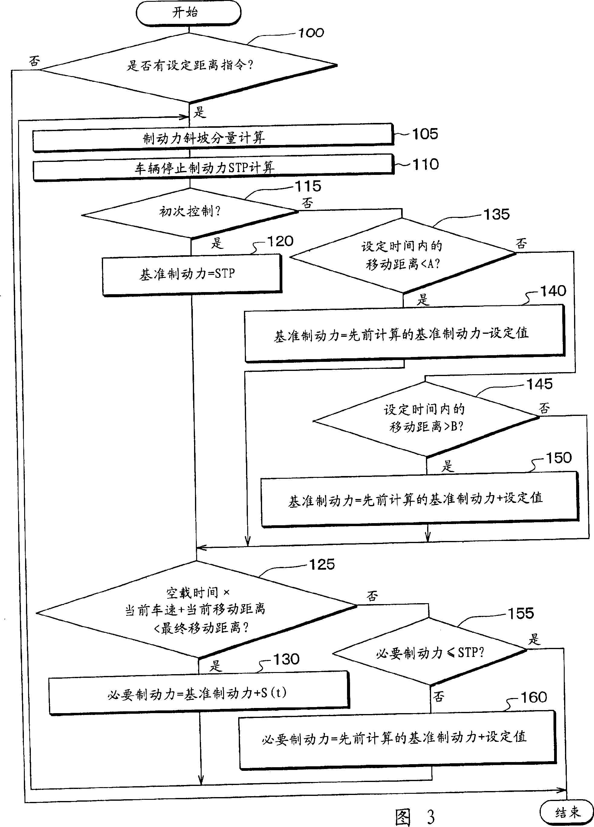
[0114] A second embodiment of the present invention will be described. In the first embodiment described above, the braking force is adjusted in order to disturb the balance between the braking force and the driving force generated in the vehicle VL, which in turn causes the vehicle VL to move only a set distance. However, in the second embodiment, the driving force is adjusted in order to achieve the same operation and effect as the first embodiment. Note that the difference in this embodiment is only that processing is performed by the parking assist control ECU 8 . The parking assist control system is the same as that in the first embodiment, therefore, only different parts will be described.

[0115] Also, in the present embodiment, upon receiving a request to perform parking assist control, the parking assist control ECU 8 calculates the final target parking position and a motion trajectory toward the target parking position, and executes parking assist control. However...


PUM


Abstract

The distance from the vehicle stop position to the target parking position is determined as the set distance. Then, the vehicle moves by gradually reducing the necessary braking force including the oscillation braking force. Thus, it is possible to run an engine-driven vehicle at an extremely low speed regardless of whether a motor is provided.

Description

technical field [0001] The present invention relates to a vehicle traveling control device capable of traveling a vehicle at an extremely low speed (for example, 0.1 to 0.2 km / h). More specifically, the present invention relates to a vehicle travel control device capable of moving a vehicle at an extremely low speed to precisely move the vehicle a set minute distance and then stop the vehicle, in some cases the parking assist control is set several centimeters to a tiny movement distance of tens of centimeters. Background technique [0002] In practice, a parking assist control that guides the vehicle into a parking space or the like is used. According to this parking assist control, the vehicle travels at a speed set by the driver to guide the vehicle to a position where the driver wants to park. Given the inertia of the vehicle and the response delays in the hardware mechanisms that generate the braking force to stop the vehicle, the vehicle must be traveling at a very l...

Claims


Application Information

Patent Timeline
Patent Type & Authority Applications(China)
IPC IPC(8): F02D29/02
CPCB60W30/18063B60W10/184B60W10/06
Inventor 森雪生神谷和宏
Owner ADVICS CO LTD
Why Eureka
Try Eureka