Check patentability & draft patents in minutes with Patsnap Eureka AI!

Backlight module

A backlight module, back frame technology, applied in optics, nonlinear optics, instruments, etc., can solve problems such as internal lamp rupture

Inactive Publication Date: 2007-01-31
AU OPTRONICS CORP
View PDF0 Cites 3 Cited by
  • Summary
  • Abstract
  • Description
  • Claims
  • Application Information

AI Technical Summary

Problems solved by technology

[0007] Therefore, the main purpose of the present invention is to provide a backlight module, so as to improve the problem that the internal lamp tube is easily broken due to the poor configuration of the high-voltage line and the low-voltage line in the traditional backlight module.

Method used


Image

  • Backlight module
  • Backlight module
  • Backlight module

Examples


Embodiment Construction

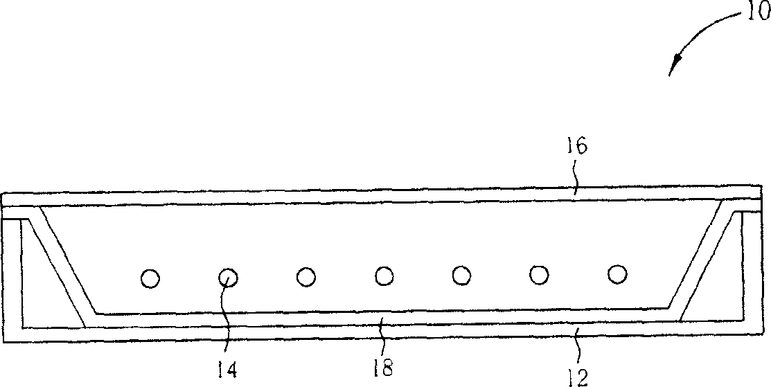
[0034] According to a preferred embodiment of the present invention, the backlight module of the present invention includes a back frame, a plurality of lamp modules disposed in the back frame, and an optical component disposed at the opening of the back frame. Wherein, the optical component can be a light guide mechanism, a diffusion sheet, a prism sheet or a combination of the above, and the backlight module can further include a reflection plate disposed on the inner surface of the back frame to reflect the light emitted by the lamp module.

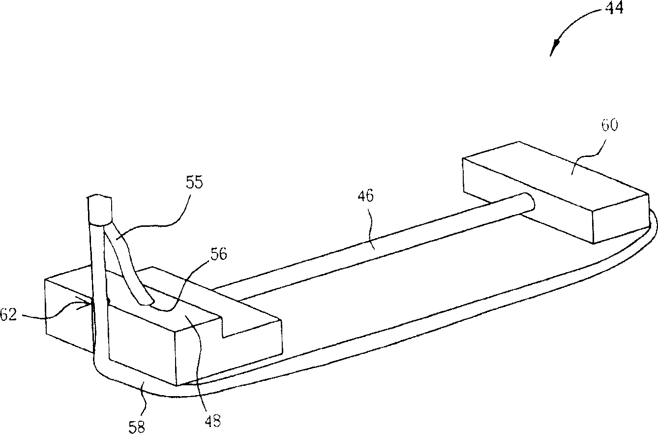
[0035] Please refer to image 3 , image 3 It is a schematic diagram of a lamp module 44 in a preferred embodiment of the present invention. like image 3 As shown, the lamp module 44 includes a lamp 46 and a lamp bracket 48 for supporting the lamp 46 . Wherein, the lamp 46 can be a linear light source such as a cold cathode fluorescent lamp (CCFL) or an external electrode fluorescent lamp (EEFL). According to a preferred embodimen...


PUM


Abstract

The invention relates to backlight module that includes luminous tube, a first cable connecting to the first end of the luminous tube, and a second cable connecting to the second end of the tube, and a luminous bracket. The bracket includes a groove. The second cable is extending from the second end to the first end and fixed in the groove.

Description

technical field [0001] The invention relates to a backlight module. Background technique [0002] With the increasingly sophisticated manufacturing technology of liquid crystal display panels, liquid crystal displays have been widely used in digital cameras, digital personal assistants (PDAs), satellite navigation systems, and flat and thin TVs. Among them, the backlight module is one of the key components of the liquid crystal display. [0003] Generally speaking, the backlight module is arranged under a liquid crystal display panel, and uses at least one light source generator, such as a lamp tube, and a combination of various optical elements (such as a diffuser plate, a prism, etc.) to provide a high The brightness and uniform light source, and then by controlling the pixel electrodes on the LCD panel to form an appropriate color, and then constitute the bright image observed by the user of the LCD display. In addition, according to the position of the light source, th...

Claims


Application Information

Patent Timeline
IPC IPC(8): G02F1/13357G02F1/133G02F1/1335
Inventor 杨诏棠黄教忠
Owner AU OPTRONICS CORP
Features
  • R&D
  • Intellectual Property
  • Life Sciences
  • Materials
  • Tech Scout
  • Unparalleled Data Quality
  • Higher Quality Content
  • 60% Fewer Hallucinations
Learn More