Spinning spindle assembly with damping device

A spindle and component technology, applied in the field of spindle components, can solve problems such as damping

Inactive Publication Date: 2007-02-07
LAKSHMI MACHINE WORKS
View PDF3 Cites 5 Cited by
  • Summary
  • Abstract
  • Description
  • Claims
  • Application Information

AI Technical Summary

Problems solved by technology

The work produced results in damping of the vibrations in the spinning or twisting spindle

Method used


Image

  • Spinning spindle assembly with damping device
  • Spinning spindle assembly with damping device
  • Spinning spindle assembly with damping device

Examples


Embodiment Construction

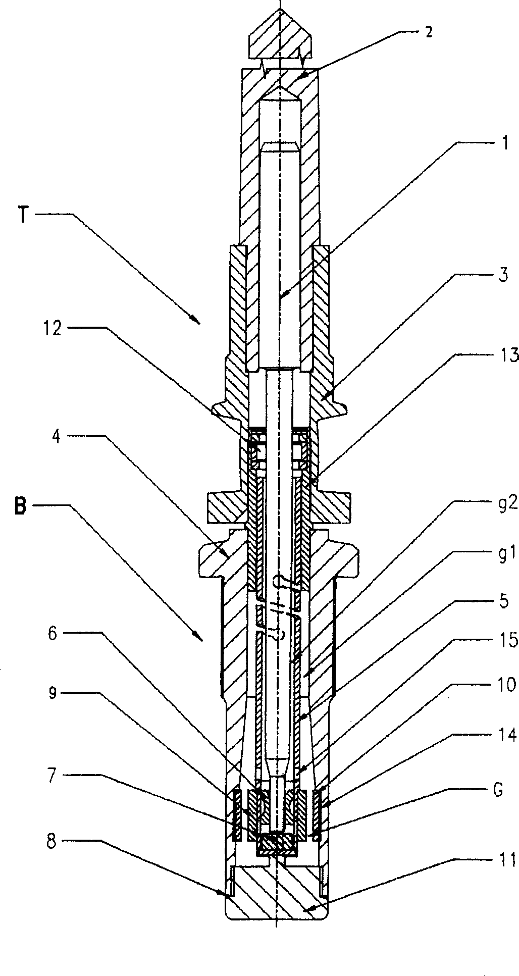
[0020] Accordingly, the present invention provides a spindle assembly, the detailed description of which is initially incorporated by reference to figure 1 &3 explain. The spindle assembly consists of a top part T and a bottom part B. The top part comprises a spindle bar 1 and a conical part 2 made of a lightweight material such as aluminium, which is rigidly fitted to the spindle bar 1 . The bottom part of the conical part is further fitted with the spindle part 3 for radially coupling the cylindrical member of the drive belt to couple the rotational movement to the top part T of the spindle.

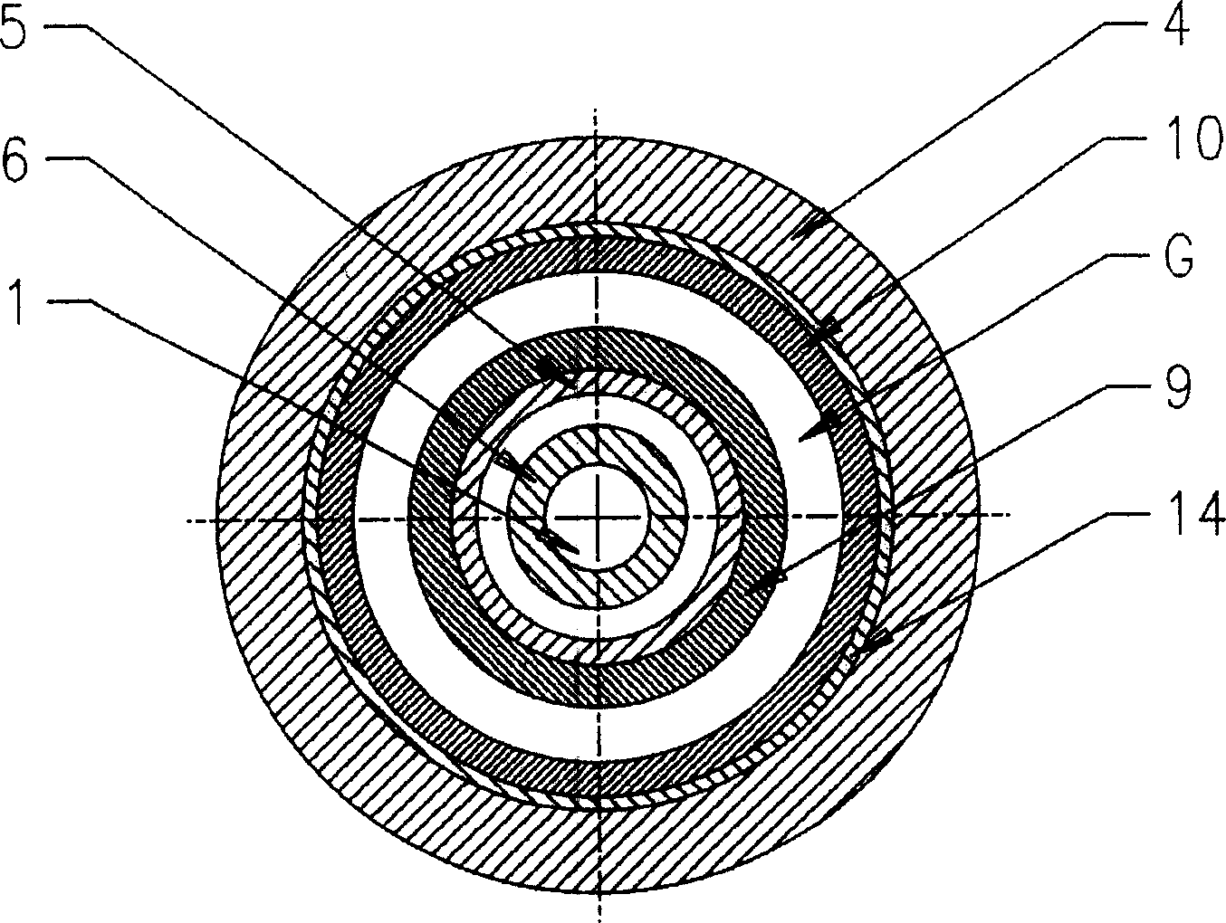
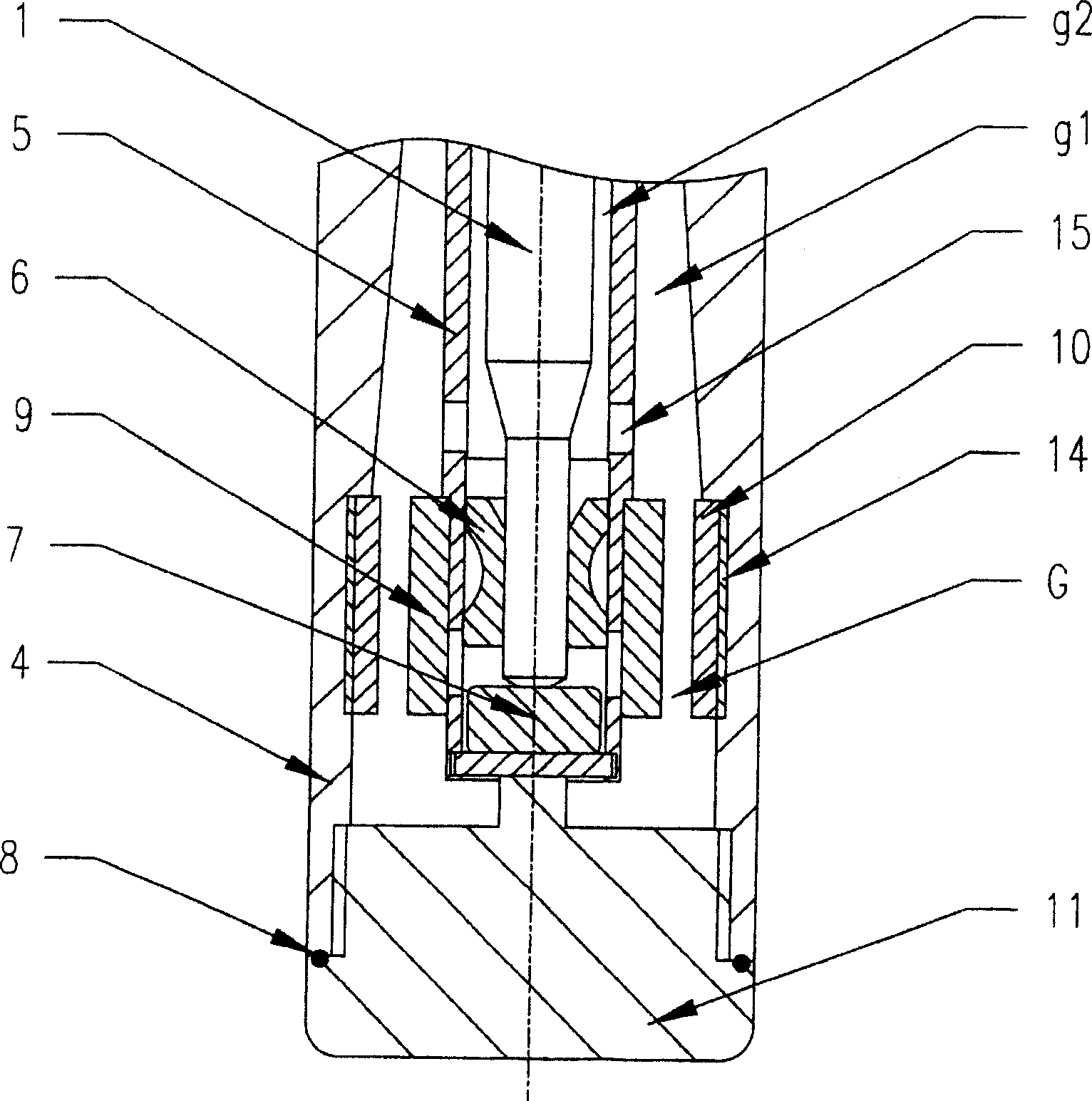
[0021] The bottom part B comprises a spindle foot 4 which houses a spindle insertion assembly 13 . The spindle insert assembly 13 is press fit to the spindle foot 4 as a supporting element. The spindle insert assembly 13 includes an intermediate bearing 12 fitted on top of it and a centering sleeve 5 fitted next to the intermediate bearing 12 . The bottom of the centering sleeve 5 ...


PUM


Abstract

A spindle assembly for spinning and twisting machine which includes: a top components; a rotary spindle blade with the top parts disposing on the top components; a spindle pedestal; a centering sleeve designed for containing the bottom of the spindle blade disposed on the spindle pedestal; at least one permanence magnet connected to the centering sleeve and at least one permanence magnet connected to the inner surface of the spindle pedestal, an air gap is provided between the two permanence magnets. the polarity of the permanence magnets are arranged to generate a repulsion force. The centering sleeve deviates from the original position in accordance with the mass imbalance generated during the cop forming process when the spindle rotates, as a result, the deviation generates a repulsive magnetic force pushing the centering sleeve to the revolving spindle, the axes of the centering sleeve and the spindle are aligned to provide a damping effect to the spindle assembly.

Description

technical field [0001] The invention relates to a spindle assembly of a textile spinning and twisting machine. In particular, the invention relates to spindle assemblies with magnetically damped spindle bars. Background technique [0002] Known spindles for spinning and twisting machines comprise an upper part and a bottom part. The upper part is constructed to have a shaft portion rotatably supported in the bottom portion, and a conical part connected to the upper part to carry a conical bobbin on which the yarn is wound. The bottom part includes an intermediate bearing and a vertical shaft bearing to rotatably support the shaft part of the upper part. The bottom part also includes an outer cover secured to the lower leg and an inner cover that accommodates the intermediate bearings and vertical shaft bearings via support members. The inner cover is separated from the outer cover by an annular gap. [0003] Textile spindles in spinning and twisting machines are operated...

Claims


Application Information

Patent Timeline
Patent Type & Authority Applications(China)
IPC IPC(8): D01H7/04
Inventor 桑杰·贾亚瓦尔圣万卢佩里阿萨密·拉克希米·那里斯汉
Owner LAKSHMI MACHINE WORKS
Why Eureka
Try Eureka