
Cryogenic distillation method and installation for air separation

An air separation and air technology, applied in lighting and heating equipment, cold treatment separation, refrigeration and liquefaction, etc., can solve the problem of low thermal efficiency

Inactive Publication Date: 2007-02-07
LAIR LIQUIDE SA POUR LETUDE & LEXPLOITATION DES PROCEDES GEORGES CLAUDE
View PDF4 Cites 4 Cited by
  • Summary
  • Abstract
  • Description
  • Claims
  • Application Information

AI Technical Summary

Problems solved by technology

[0003] These known devices are not very thermally efficient, since the heat inflow associated with cryogenic compression has to be rejected

Method used


Image

  • Cryogenic distillation method and installation for air separation
  • Cryogenic distillation method and installation for air separation

Examples


Embodiment Construction

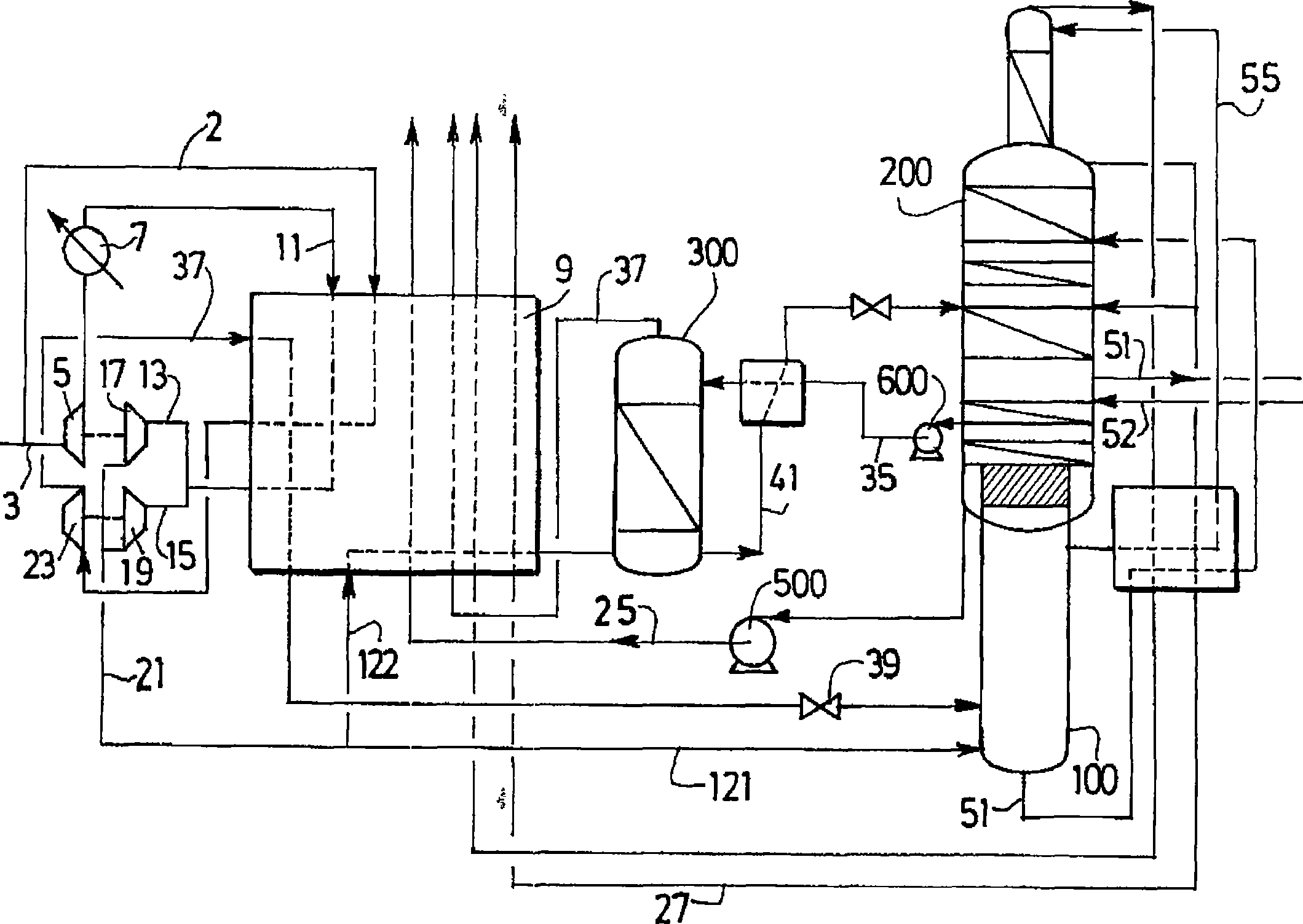
[0049] exist figure 1 , the air flow at atmospheric pressure is compressed to about 15 bar in a main compressor (not shown). The air is then optionally cooled before being purified (not shown) to remove impurities. Divide the purified air into two parts. A portion 3 of the air is sent to the booster 5 where it is compressed to a pressure between 17 and 20 bar, then the boosted air is sent to the warm end of the main exchange line 9 of the air separation plant Cooled by water cooler 7 before. The charge air 11 is cooled to an intermediate temperature before leaving the exchange line and being divided into two parts. Of course, a portion of stream 11 may continue to be cooled until it reaches the cold end of exchange line 9 from which it is liquefied and discharged. One portion 13 is sent to turbine 17 and the remaining portion 15 is sent to turbine 19. The two turbines have the same intake air temperature and pressure and the same exhaust temperature and pressure, but of c...


PUM


Abstract

Separation of air is obtained by vaporization of pressurised liquid in an exchange line of a air separation unit by heat exchange with a compressed gas at a cryogenic temperature. - The process is carried out in an installation comprising a double or triple air separation column operating at a high pressure and with an exchange line, in which - (1) all the air is raised to high pressure, greater by at least 5 bars to the mean pressure, and purified; - (2) part of the air flow is cooled in the exchanger and divided into two fractions; - (3) each fraction is expanded in a turbine; - (4) the inlet pressure of each turbine is greater by 5 bars to the mean pressure; - (5) the exhaust pressure is equal to the mean pressure; - (6) part of the air expanded in one of the turbines is sent to the double or triple column; - (7) a cold compressor, mechanically connected to one of the expansion turbines aspirates air, which has been cooled in the heat exchanger, and exhausts air at a temperature higher than the inlet temperature, the fluid thus compressed being re-introduced in the exchanger in which part condenses; - (8) at least one liquid from the column is vaporized in the heat exchanger. - The turbine not coupled to the cooled compressor is coupled to a compressor followed by a refrigerant, and, optionally, the temperature of aspiration of the cold compressor approximates to the temperature of vaporization of the liquid. - An INDEPENDENT CLAIM is also included for the installation of the process.

Description

technical field [0001] The present invention relates to a method and apparatus for separating air by cryogenic distillation. Background technique [0002] It is known to produce gas from pressurized air by gasification of pressurized liquid by heat exchange with compressed gas above cryogenic temperature in the exchange line of an air separation plant. Devices of this type are known from FR-A-2688052, EP-A-0644388, EP-A-1014020 and patent application FR 03 / 01722. [0003] The thermal efficiency of these known devices is not very high because the heat influx associated with cryogenic compression must be removed. [0004] In addition, in the case of the solution shown in Fig. 7 such as US-A-5475980, the entire turbine connected to the low temperature supercharger is associated with an energy absorption system (oil brake) integrated on the shaft of the machine, and technically Limited to low power levels (around 70kW). [0005] Regardless, this type of approach is indeed eco...

Claims


Application Information

Patent Timeline
Patent Type & Authority Applications(China)
IPC IPC(8): F25J3/04
CPCF25J3/04393F25J2200/04F25J3/04296F25J2240/04F25J3/04303F25J3/0446F25J2215/52F25J3/04175F25J2200/06F25J3/0409F25J2235/50F25J3/04054F25J3/0429F25J2215/54F25J3/04466F25J3/04387F25J2240/10
Inventor P·勒博
Owner LAIR LIQUIDE SA POUR LETUDE & LEXPLOITATION DES PROCEDES GEORGES CLAUDE
Learn More