Eureka AIR delivers breakthrough ideas for toughest innovation challenges, trusted by R&D personnel around the world.

Electronic ballast with transformer interface

A technology of electronic ballasts and transformers, applied in the direction of electric light sources, electrical components, lamp circuit layout, etc., can solve the problems of expensive optocouplers, increased manufacturing and retail costs, etc.

Inactive Publication Date: 2007-02-07
KONINKLIJKE PHILIPS ELECTRONICS NV
View PDF0 Cites 1 Cited by
  • Summary
  • Abstract
  • Description
  • Claims
  • Application Information

AI Technical Summary

Problems solved by technology

An optocoupler interface typically draws 1-2 mA, which limits the number of electronic ballasts on the bus to around 64
And optocouplers are expensive, adding to manufacturing and retail costs

Method used


Image

  • Electronic ballast with transformer interface
  • Electronic ballast with transformer interface
  • Electronic ballast with transformer interface

Examples


Embodiment Construction

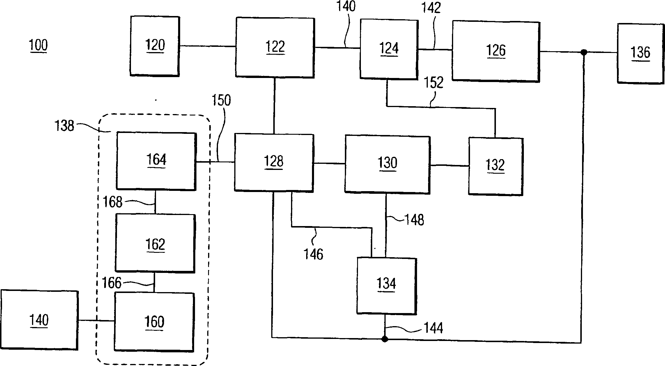
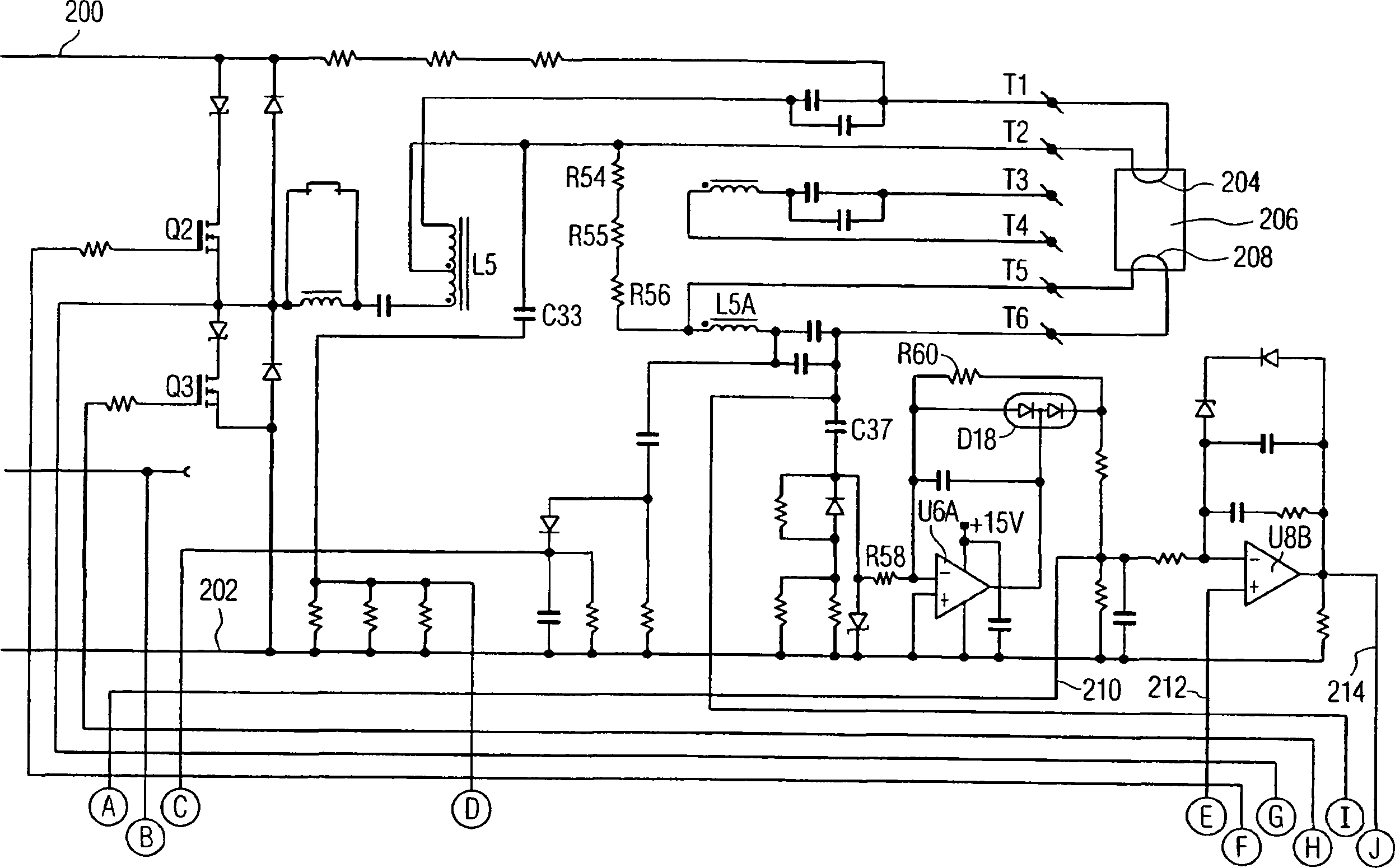
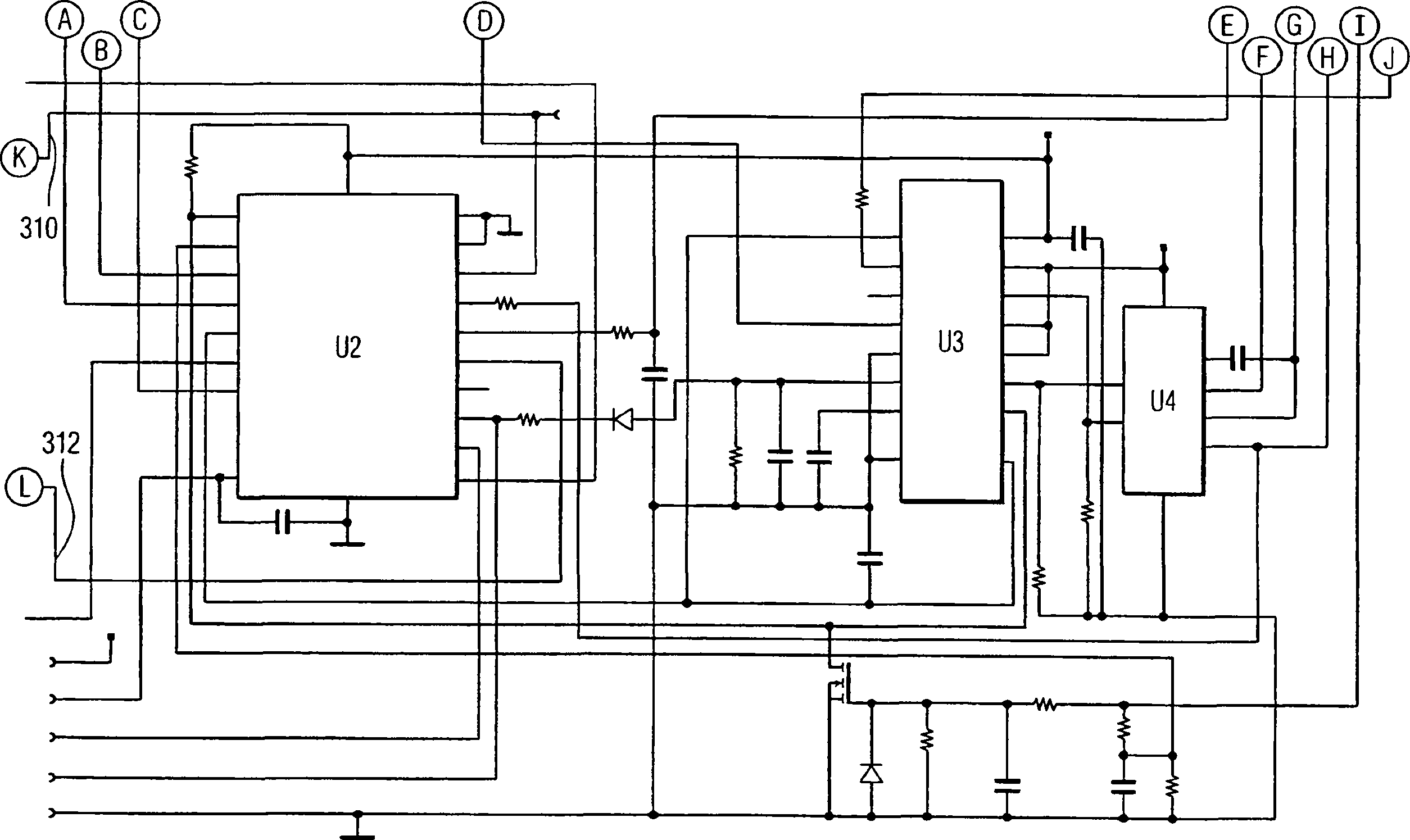
[0017] figure 1 It is a block diagram of an electronic ballast with a transformer interface manufactured according to the present invention. Electronic ballast 100 includes AC / DC converter 122, half bridge 124, resonant tank 126, microprocessor 128, regulating pulse width modulator (PWM) 130, high voltage (HV) driver 132, error circuit 134 and filament current sense Test circuit 138. AC / DC converter 122 receives mains voltage 120 and resonant tank 126 supplies power to lamp 136 . The external signal 140 is sent and received between the communication interface circuit 138 and an external control system (not shown).

[0018] The main voltage 120 is the AC line voltage provided to the electronic ballast 100 , such as 120 volts, 127 volts, 220 volts, 230 volts or 277 volts. AC / DC converter 122 receives mains voltage 120 . The AC / DC converter 122 converts the AC main voltage 120 into a DC voltage 140 and provides it to the half bridge 124 . AC / DC converter 122 typically includ...


PUM


Abstract

An electronic ballast with transformer interface communicating between an external control system and the electronic ballast comprises an outboard circuit (160) operably connected to the external control system and communicating with the external control system by an external signal (140); a transformer (162) being operably connected to the outboard circuit (160) and communicating with the outboard circuit by an outboard signal (166); and an inboard circuit (164) being operably connected to the transformer (162), communicating with the transformer (162) by an inboard signal (168), and communicating with a microprocessor (128) by an internal signal (150). The external signal (140) can use the Digital Addressable Lighting Interface (DALI) protocol. The in board signal (168) can have a lower duty cycle and a higher duty cycle on the primary winding to generate a lower voltage and a higher voltage, respectively, for the outboard signal (166) on the secondary winding.

Description

technical field [0001] The invention relates to an electronic ballast for a gas discharge lamp, in particular to an electronic ballast with a transformer interface. Background technique [0002] Gas discharge lamps such as fluorescent lamps require a ballast to limit the lamp current. Electronic ballasts are increasingly widely used due to their numerous advantages. Electronic ballasts provide 15%-20% higher efficiency than magnetic ballast systems. Electronic ballasts generate less heat, reducing cooling load requirements and operate more quietly without "humming". In addition, electronic ballasts offer more flexibility in design and control. [0003] Electronic ballasts must work with different supply voltages, different types of lamps and different numbers of lamps. The power grid determines that the power supply voltage is different around the world, and the power supply voltage at a location may also vary. Different types of lamps may have the same physical dimensi...

Claims


Application Information

Patent Timeline
IPC IPC(8): H05B37/02H05B41/36
CPCH05B41/36H05B37/0254H05B47/18
Inventor W·L·凯思G·L·格劳伊K·E·格劳塞
Owner KONINKLIJKE PHILIPS ELECTRONICS NV
Why Eureka
Eureka Blog
Learn More