

Operation mechanism of engine hood
A technology of operating mechanism and cover, applied in building structure, construction, door/window accessories, etc., can solve the problems of limited opening space of cover, inconvenient operation, inconvenient maintenance of engine or related parts, etc.
- Summary
- Abstract
- Description
- Claims
- Application Information
AI Technical Summary
Problems solved by technology
Method used
Image

Examples
no. 1 approach
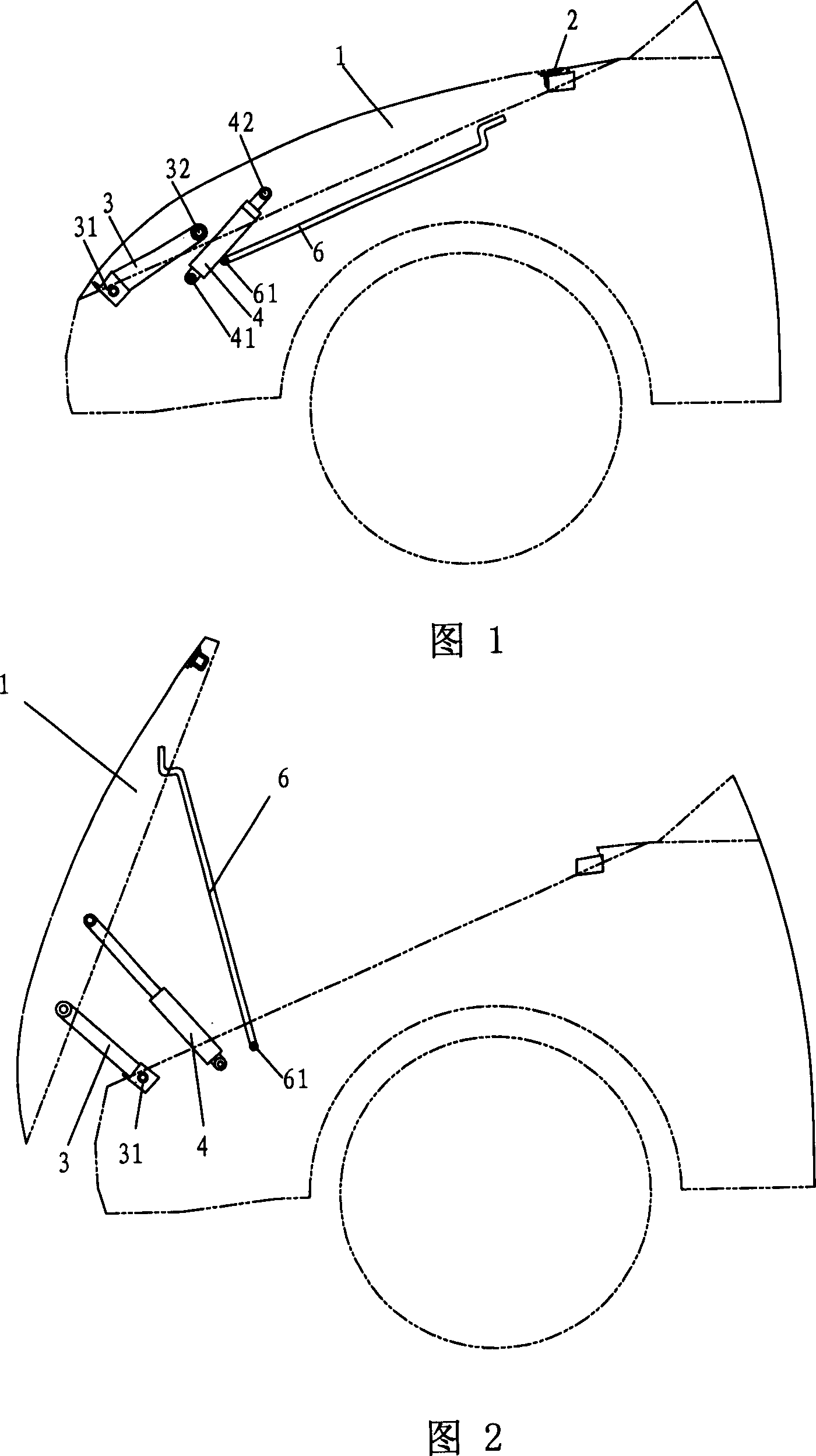
[0046] Fig. 1 is a cross-sectional view of a cover operating mechanism according to a first embodiment of the present invention, wherein the cover is in a closed state; Fig. 2 is a view of a state in which the cover is opened in Fig. 1 .
[0047] As shown in Figure 1, the hood operating mechanism has a hood 1 and a hood locking device 2, and also includes a support rod 3 and a drive device 4, wherein the drive device 4 is located at the back of the support rod 3 (that is, the side near the driver's cab) ), the lower ends of the support rod 3 and the driving device 4 are respectively hinged on the automobile body, and the upper ends are respectively hinged on the machine cover 1.
[0048] As can be seen from Fig. 1, the rear end of the machine cover 1 (that is, the end near the driver's cab) has a cover locking device 2, which is used to lock the machine cover 1 firmly on the vehicle body under the normal state of the vehicle. It can prevent the machine cover 1 from opening aut...
no. 2 approach
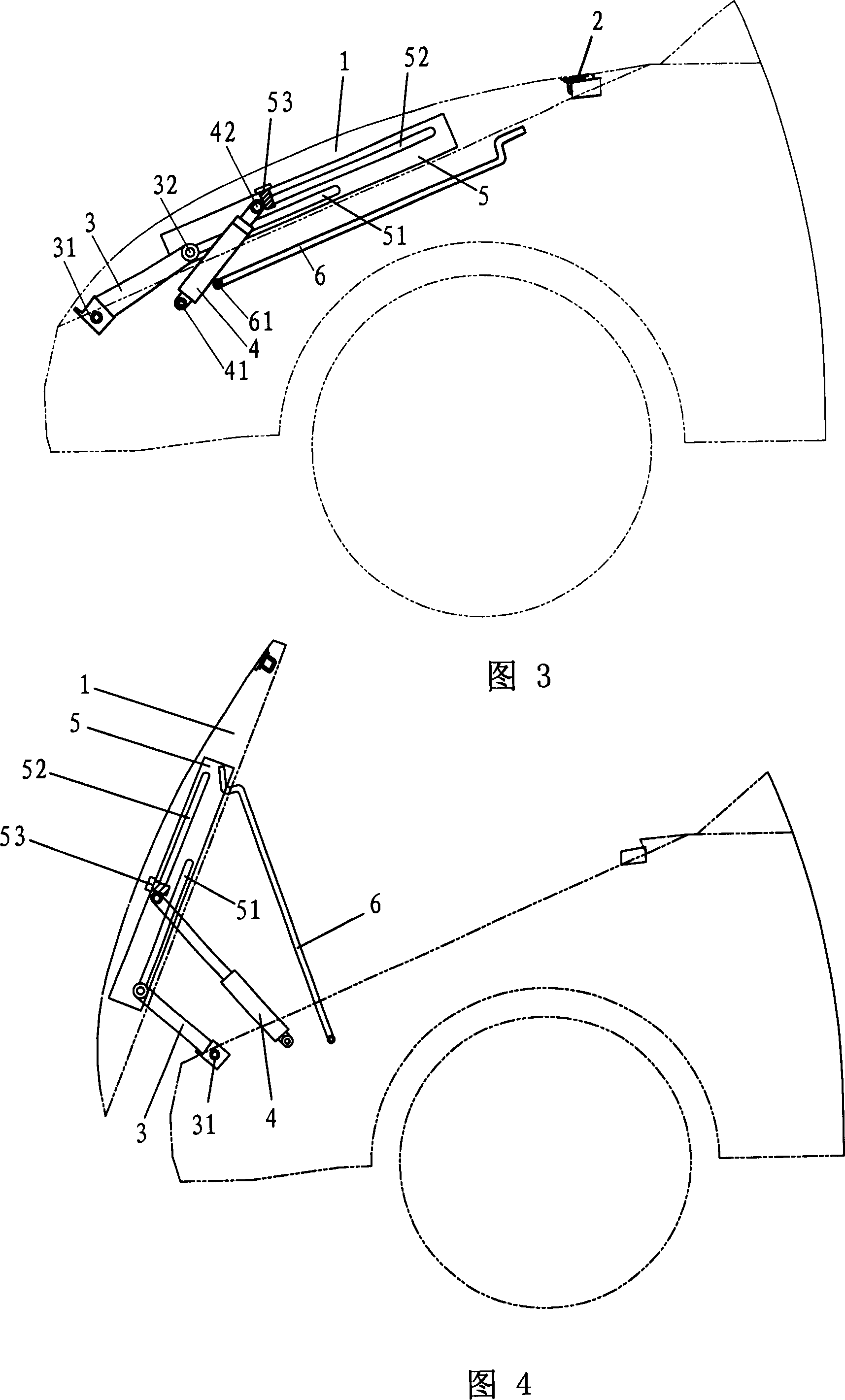
[0060] Fig. 3 is a sectional view of the cover operating mechanism according to the second embodiment of the present invention; Fig. 4 is a state view of the cover in Fig. 3 being opened.
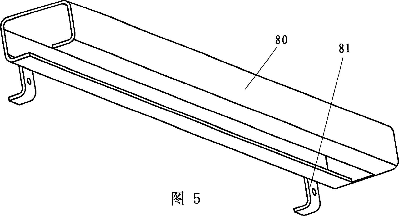
[0061] As shown in Figures 3 and 4, the hood operating mechanism in this embodiment has a hood 1 and a hood locking device 2, and also includes a support rod 3, a hydraulic cylinder 4 and a support beam 5, wherein the hydraulic cylinder 4 is positioned on the support Behind the rod 3, the support beam 5 is fixed on the machine cover 1, and the support beam 5 is provided with slide rails along the longitudinal direction. inside the track.
[0062] Preferably, the slide rails are a first slide rail 51 and a second slide rail 52 arranged parallel to each other, and the upper ends of the support rod 3 and the hydraulic cylinder 4 are respectively slidably connected to the first slide rail 51 and the second slide rail. within rail 52.
[0063] In addition, a limiting device 53 may also be prov...
no. 3 approach
[0078] According to the third embodiment of the present invention, the cover operating mechanism also includes an anchor bracket 7 and a fixing seat 72. The front end of the anchor bracket 7 is hinged on the machine cover 1, and the rear end is detachably connected to the fixing seat 72. The fixing Seat 72 is then fixed on the machine cover. Join accompanying drawing to describe this foundation support in detail below.
[0079] Figure 9 is a cross-sectional view of the cover operating mechanism according to the third embodiment of the present invention; Figure 10 yes Figure 9 The state diagram of the middle machine cover being opened, wherein the opened machine cover is supported by the anchor bracket 7; FIG. 11 is a perspective view of the shell of the anchor bracket in an example of this embodiment; Figure 12 It is a schematic cross-sectional view of the anchor bracket part in this embodiment; Figure 13 is a schematic plan view of the foot bracket part in this embod...
PUM
 Abstract
Description
Claims
Application Information