
Rapid take up and vibration proof adjuster mechanism

一种锁定装置、调节系统的技术,应用在松弛调节器、制动器类型、制动器的部件等方向,能够解决降低制动器性能、增加制动系统松弛、制动衬块磨损等问题

Inactive Publication Date: 2007-02-14
ARVINMERITOR TECH
View PDF1 Cites 5 Cited by
  • Summary
  • Abstract
  • Description
  • Claims
  • Application Information

AI Technical Summary

Problems solved by technology

Movement can cause undesirable brake pad wear, or further increase slack in the brake system, which reduces brake performance

Method used


Image

  • Rapid take up and vibration proof adjuster mechanism
  • Rapid take up and vibration proof adjuster mechanism
  • Rapid take up and vibration proof adjuster mechanism

Examples


Embodiment Construction

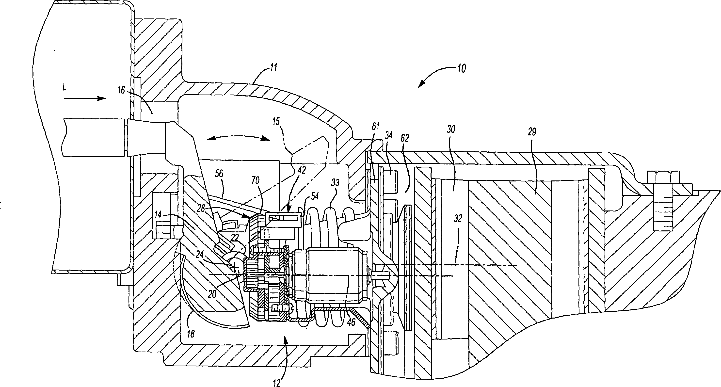
[0036] figure 1 A disc brake assembly 10 employing the slack adjustment system 12 of the present invention is illustrated. The disc brake assembly 10 has a frame 11 that surrounds the internal components and takes the loads they create. As the driver operates a brake (not shown), an input load (illustrated by arrow L) is transferred to the control rod 14 through an opening 16 in the frame 11 . The lever 14 is rotatably supported by the frame 11 through a bearing 18 . The applied input load L rotates the control rod 14 about the control rod axis 20 . That is, if figure 1 As shown, the lever 14 rotates clockwise about the lever axis 20 .

[0037] A cylindrical roller 22 is recessed into the base of the lever 14 . The roller 22 is arranged eccentrically with respect to the center of rotation of the lever 14 . That is, the roller 22 rotates about a roller axis 24 that is offset from the lever axis 20 . When the input load L causes the lever 14 to rotate about the lever axis...


PUM


Abstract

The invention discloses a slack adjustment system for a disk brake which includes a biasing member to adjust slack in a brake system. The biasing member operates independently of pressure applied to a brake actuator. A locking device secures the adjustment mechanism in place when adjustment is not necessary. Release of the locking member allows the biasing member to adjust the resting position of brake pads independent of driver applied brake pressure.

Description

Background technique [0001] This application is a continuation-in-part of US Patent Application Serial No. 10 / 355,511, filed January 31,2003. [0002] The invention relates to an adjuster device for a brake. [0003] As the brake pads or the brake disc wear, the spacing between the brake pad and the brake disc increases. As the space between the brake pad and brake disc increases, the brake actuator must move farther to engage the brake. In other words, there is more slack when braking, resulting in less efficient braking. To compensate for slack, the slack adjuster device moves the brake pads closer to the brake disc prior to brake engagement. This adjustment ensures that the amount of actuator movement is consistent even as the brake pads wear. [0004] Conventional brake adjuster devices employ fairly complex mechanical components to perform this function. Typically force from a brake actuator is used to actuate the regulator means, which reduces braking effectiveness ...

Claims


Application Information

Patent Timeline
Patent Type & Authority Applications(China)
IPC IPC(8): F16D65/54F16D65/14F16D65/56
CPCF16D2125/64F16D2121/14F16D2125/28F16D65/568F16D2125/32F16D2125/70
Inventor 马克·安东尼·诺曼马丁·泰勒
Owner ARVINMERITOR TECH
Features
  • Generate Ideas
  • Intellectual Property
  • Life Sciences
  • Materials
  • Tech Scout
  • Unparalleled Data Quality
  • Higher Quality Content
  • 60% Fewer Hallucinations
Learn More