Outside-rotor motor

A technology of external rotor motor and stator yoke, which is applied in the direction of electrical components, electromechanical devices, electric components, etc., and can solve the problems of motor characteristic degradation and poor reliability

Inactive Publication Date: 2007-02-14
SHINANO KENSHI
View PDF1 Cites 13 Cited by
  • Summary
  • Abstract
  • Description
  • Claims
  • Application Information

AI Technical Summary

Problems solved by technology

When an insulating material is provided and / or a space is provided in the stator yoke, the volume of the coil or the yoke is reduced, the motor characteristics are degraded and the insulation has poor reliability

Method used


Image

  • Outside-rotor motor
  • Outside-rotor motor
  • Outside-rotor motor

Examples


Embodiment Construction

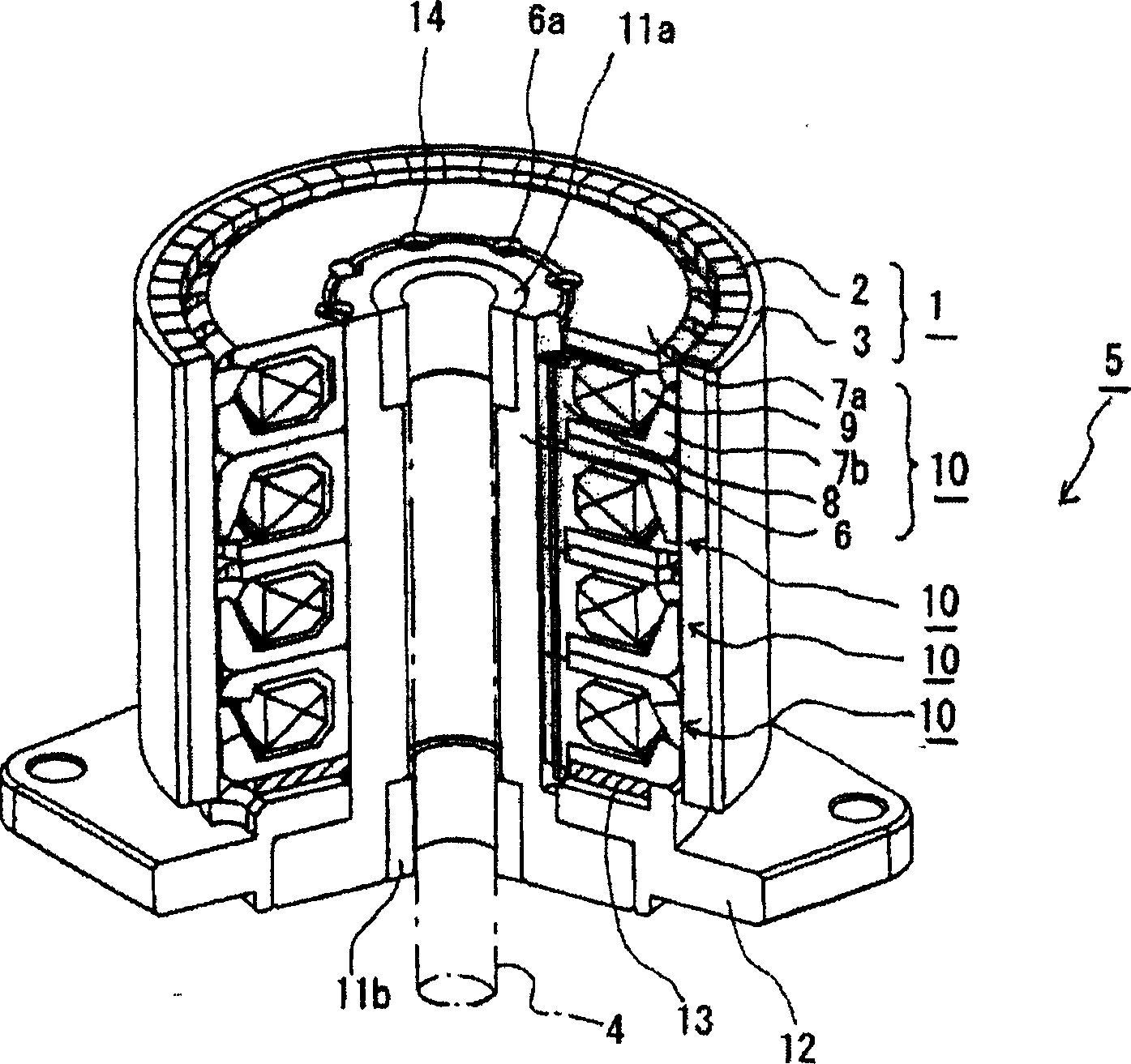
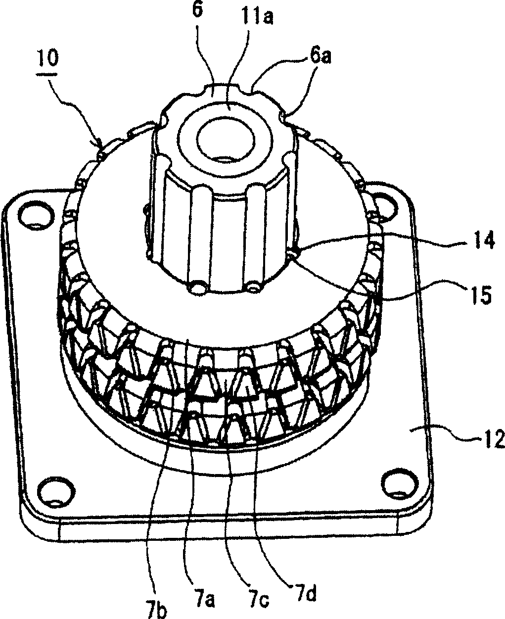
[0039] Preferred embodiments of an outer rotor motor according to the present invention will now be described with reference to the accompanying drawings. The outer rotor motor according to the present invention is a claw pole type motor in which a plurality of stator units are coaxially stacked inside the stator, each stator unit is formed such that a coil is sandwiched by a stator yoke, and claw poles are engaged with each other.

[0040] An outer rotor motor will now be described using a two-phase stepping motor used in OA appliances, computer peripherals, automobiles, transmission equipment related to FA (factory automation), and the like.

[0041] will now refer to figure 1 Describe the overall structure of a two-phase stepper motor. exist figure 1 In this, the rotor 1 is constructed such that a permanent magnet 2 is provided on the inner peripheral surface of a rotor yoke 3 in a cylindrical form, the permanent magnet 2 having been magnetized with alternating N and S po...


PUM


Abstract

An outer rotor motor is miniaturized, is easier to assemble, and lead ends can be insulated with improved reliability without a drop in motor characteristics. One or a plurality of concave channels provided in the axial direction in a circumferential surface of a housing and one or a plurality of rotation-stopping portions that engage the concave channels are provided in a surface of each coil bobbin that faces the cylinder. Through-holes are provided in the rotation-stopping portions in parallel with the rotor shaft.

Description

technical field [0001] The present invention relates to an external rotor motor used for an OA appliance such as a copying machine or a printer, computer peripherals, automobiles, transmission equipment related to FA (Factory Automation), and the like. Background technique [0002] In a motor, a rotor equipped with permanent magnets is disposed to face magnetic poles of a stator, and the rotor is caused to rotate by switching the direction of current passing through a plurality of coils disposed in a stator unit. The coils are connected to a motor's circuit board to switch the direction of the current. As an example, in the case of an ordinary brushless motor, the winding direction of the coils on the stator core is set so that the coils are wound parallel to the output shaft (i.e., so that the winding core direction is perpendicular to the axial direction), and the starting point of the winding Both the lead terminal and the coil winding terminal extend outward in the axia...

Claims


Application Information

Patent Timeline
Patent Type & Authority Applications(China)
IPC IPC(8): H02K37/14
CPCH02K1/145H02K37/12H02K1/187
Inventor 臼井弘明
Owner SHINANO KENSHI
Why Eureka
Try Eureka