Actuator

A driver and driven technology, used in instruments, generators/motors, piezoelectric effect/electrostrictive or magnetostrictive motors, etc., can solve the problem of unstable friction between driven parts and driving friction parts Driven parts move, it is difficult to obtain the thrust of the driven parts, etc., to achieve stable drive control and ensure the effect of thrust

Inactive Publication Date: 2007-02-14
FUJI PHOTO OPTICAL CO LTD
View PDF1 Cites 1 Cited by
  • Summary
  • Abstract
  • Description
  • Claims
  • Application Information

AI Technical Summary

Problems solved by technology

[0005] However, in conventional actuators, the frictional force between the driven part and the driving friction part is unstable, so there is a problem that the driven part cannot be moved at a stable speed and thrust.
[0006] In addition, in the conventional actuator, the contact area between the driven member and the driving friction member is small, so there is a problem that it is difficult to obtain sufficient thrust of the driven member.

Method used


Image

  • Actuator
  • Actuator
  • Actuator

Examples


Embodiment Construction

[0024] Hereinafter, the best embodiment of the actuator according to the present invention will be described in detail with reference to the drawings.

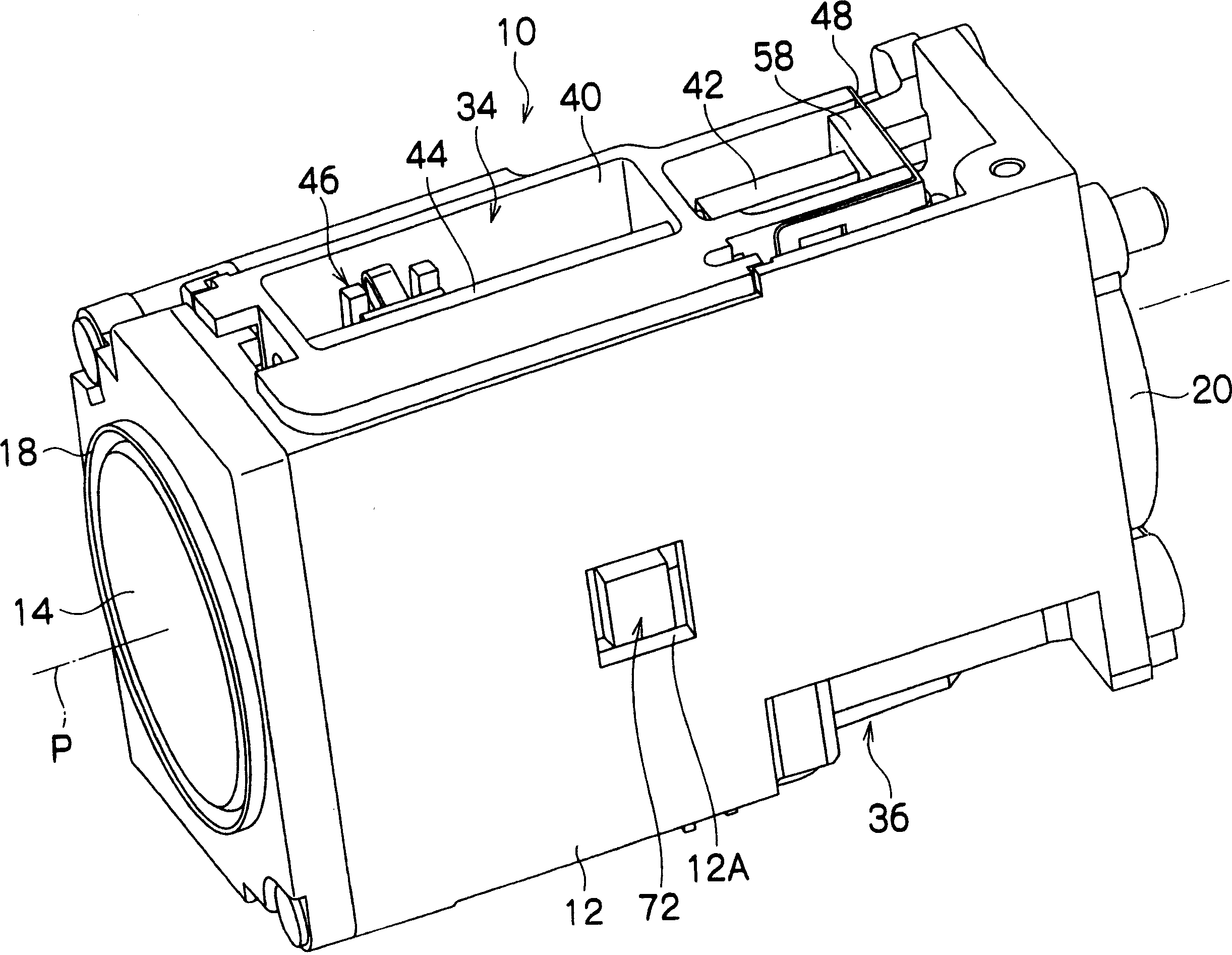
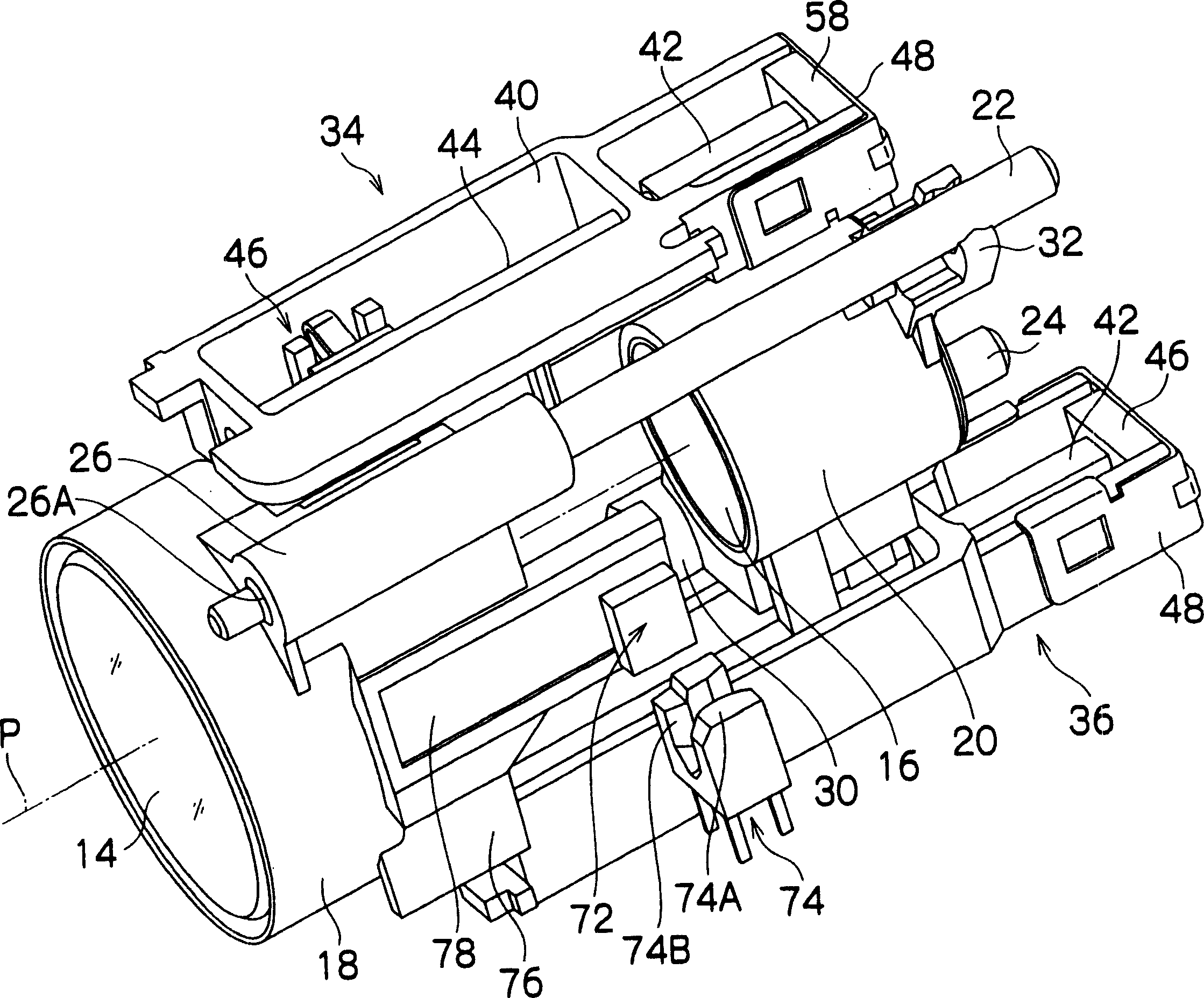
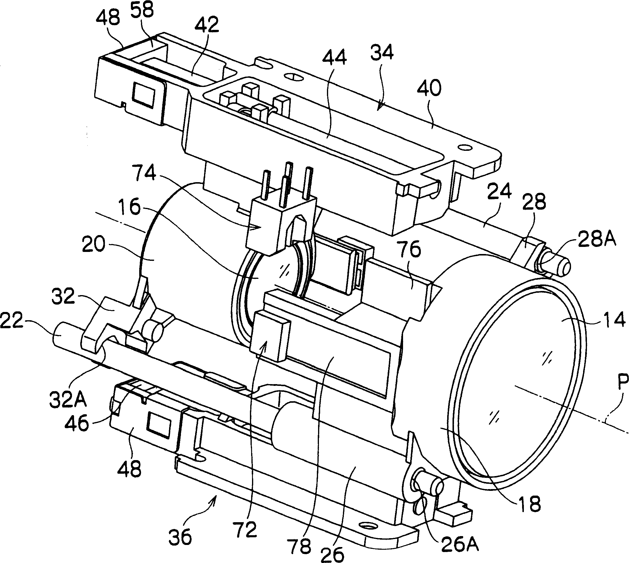
[0025] figure 1 It is a perspective view showing a lens device 10 to which an actuator according to the present invention is applied, figure 2 , image 3 It is a perspective view showing its internal structure.

[0026] Such as figure 1 As shown, the lens device 10 has a main body 12 formed in a substantially rectangular shape, and the inside of the main body 12 is equipped with figure 2 , image 3 Zoom lens (sets) 14, 16 are shown. One of the zoom lenses (groups) 14 and 16 is a zoom lens, and the other is a correction lens. Furthermore, the zoom lenses (groups) 14 and 16 are held by holding frames 18 and 20, respectively. The holding frames 18 and 20 are slidably supported in the direction of the optical axis P by two guide shafts 22 and 24 . The two guide shafts 22 and 24 are arranged at diagonal positions inside t...


PUM


Abstract

The invention provides an actuator in which stabilized drive control can be carried out by bringing a drive friction member bonded to the end face of an electromechanical conversion element in a telescopic direction into surface contact with a member sliding thereon. The actuator 34 comprises a piezoelectric element 42, a drive shaft 44 fixed to the end face 42A of the piezoelectric element 42, a coupling piece 46 engaged with the drive shaft 44, and a first sliding member 52 and a second sliding member 54 supported by the coupling piece 46 and sliding on the drive shaft 44. The first sliding member 52, the second sliding member 54 and the drive shaft 44 are arranged to come into surface contact.

Description

[0001] technology area [0002] The present invention relates to an actuator, and in particular to an actuator mounted on a small precision device such as a digital camera or a mobile phone to drive a zoom lens. Background technique [0003] As a driving device for a lens portion of a digital camera or the like, there is a driver using a piezoelectric element. For example, in the actuator of Patent Document 1, the drive shaft is fixed to one side of the piezoelectric element, and the other side of the piezoelectric element is fixed to the device main body. A lens barrel is slidably supported on the drive shaft, and the lens barrel is frictionally engaged with the drive shaft by a pushing force of a leaf spring. A driving pulse having a substantially sawtooth waveform is applied to the piezoelectric element, and the piezoelectric element deforms at different speeds in the direction of expansion and the direction of contraction. For example, if the piezoelectric element deform...

Claims


Application Information

Patent Timeline
Patent Type & Authority Applications(China)
IPC IPC(8): H02N2/00H02N2/02H02N2/04G02B7/04
CPCG02B7/102H02N2/025
Inventor 佐佐木龙太
Owner FUJI PHOTO OPTICAL CO LTD
Why Eureka
Try Eureka