Transmission device

A technology of transmission device and transmission rod, which is applied in the direction of transportation and packaging, cantilever mounted on the pivot, suspension, etc., and can solve the problem that the rotating arm is difficult to push at the same time

Active Publication Date: 2016-11-16
ANHUI HUALING AUTOMOBILE
View PDF6 Cites 0 Cited by
  • Summary
  • Abstract
  • Description
  • Claims
  • Application Information

AI Technical Summary

Problems solved by technology

[0006] In view of this, the object of the present invention is to provide a transmission device, which can effectively solve the problem that the rotating arms at both ends of the axle are difficult to push simultaneously

Method used


Image

  • Transmission device
  • Transmission device

Examples


Embodiment Construction

[0024] The embodiment of the invention discloses a transmission device to effectively solve the problem that the rotating arms at both ends of the axle are difficult to push simultaneously.

[0025] The following will clearly and completely describe the technical solutions in the embodiments of the present invention with reference to the accompanying drawings in the embodiments of the present invention. Obviously, the described embodiments are only some, not all, embodiments of the present invention. Based on the embodiments of the present invention, all other embodiments obtained by persons of ordinary skill in the art without making creative efforts belong to the protection scope of the present invention.

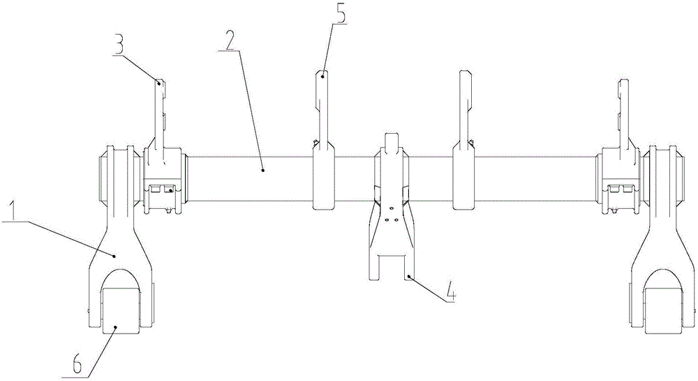
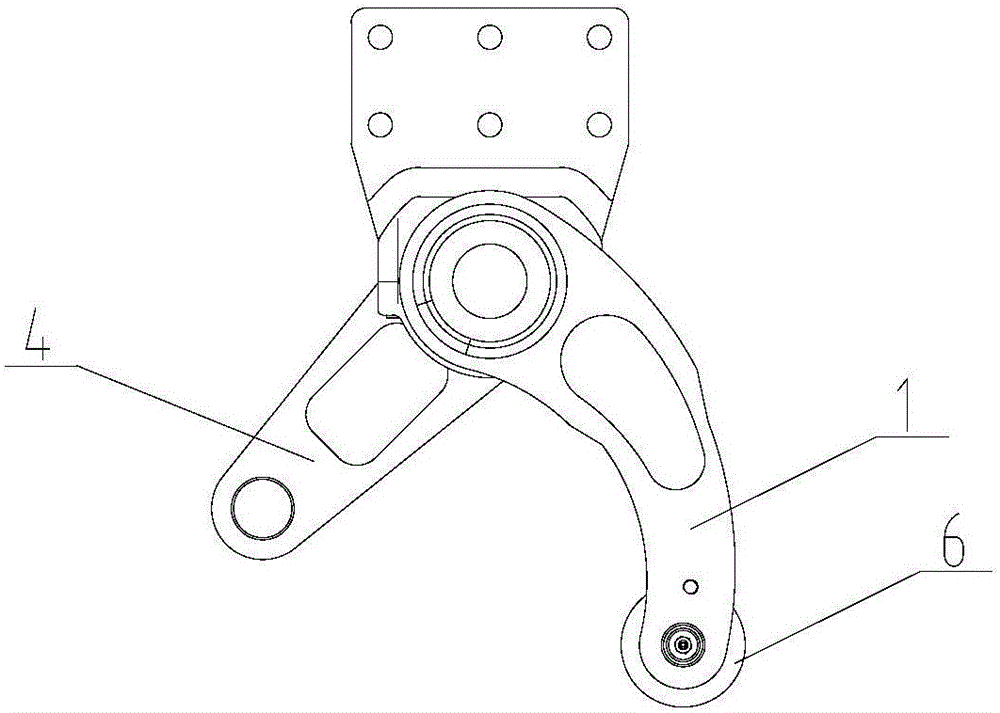
[0026] see Figure 1-Figure 2 , figure 1 Schematic diagram of the structure of the transmission device provided by the embodiment of the present invention; figure 2 for figure 1 Schematic diagram of the side view structure of the middle transmission device.

[0027] ...


PUM


Abstract

The invention discloses a transmission device which comprises push arms, a transmission rod with the two ends fixedly connected with the push arms, installation seats rotationally connected with the transmission rod in the extending direction of the transmission rod and a force arm fixedly installed at the middle portion of the transmission rod and extending in the transverse direction of the transmission rod. In the transmission device, the force arm is pushed through a push device, then the force arm drives the transmission rod to rotate according to a preset direction, and rotation of the transmission rod can drive the push arms to rotate so that the two relatively-far positions can be effectively pushed through driving of one drive mechanism. Meanwhile, through the arrangement of the force arm, the thrust of the push arms can be improved, so that it is guaranteed that the thrust of the push arms meets the requirement, and therefore the transmission device can effectively solve the problem that it is difficult to simultaneously push rotary arms at the two ends of an axle.

Description

technical field [0001] The invention relates to the field of transmission devices, more specifically, to a transmission device. Background technique [0002] In the suspension system of the vehicle, an auxiliary pushing system is often required, especially on the chassis with more than three axles. In order for the drive axle of the vehicle to be in contact with the ground as much as possible, it is necessary to properly adjust the position of the rear axle on rough roads so that the drive axle can fit the ground. [0003] Based on this, the rear axle is generally provided with a pivot arm in the prior art, and the pivot arm is rotationally connected with the beam of the vehicle. One end of the pivot arm is provided with a wheel hub, while the other end is driven by a driving part to drive it to rotate when necessary. The hub moves up and down. [0004] Because there are two wheel hubs on the axle, the balanced driving of the vehicle requires the two wheel hubs to have a c...

Claims


Application Information

Patent Timeline
IPC IPC(8): B60G7/00
CPCB60G7/008
Inventor 李献飞孙红军第海龙钱鑫于莉年淑梅朱晓红刘同宿丹丹夏晶晶张莉
Owner ANHUI HUALING AUTOMOBILE
Why Eureka
Try Eureka