Injection moulding machine

A technology for injection molding machines and molded products, applied in the field of injection molding machines, can solve problems such as large space and achieve the effect of reducing costs

Inactive Publication Date: 2007-02-21
SUMITOMO HEAVY IND LTD
View PDF2 Cites 7 Cited by
  • Summary
  • Abstract
  • Description
  • Claims
  • Application Information

AI Technical Summary

Problems solved by technology

However, when installing multiple injection molding machines, a large space is required in the molding factory
In addition, since the molding conditions of each injection molding machine are different, it is necessary to store molded products with a short cycle time in the factory, so a larger space must be prepared

Method used


Image

  • Injection moulding machine
  • Injection moulding machine
  • Injection moulding machine

Examples


Embodiment Construction

[0078] Embodiments of the present invention will be described in detail below with reference to the drawings.

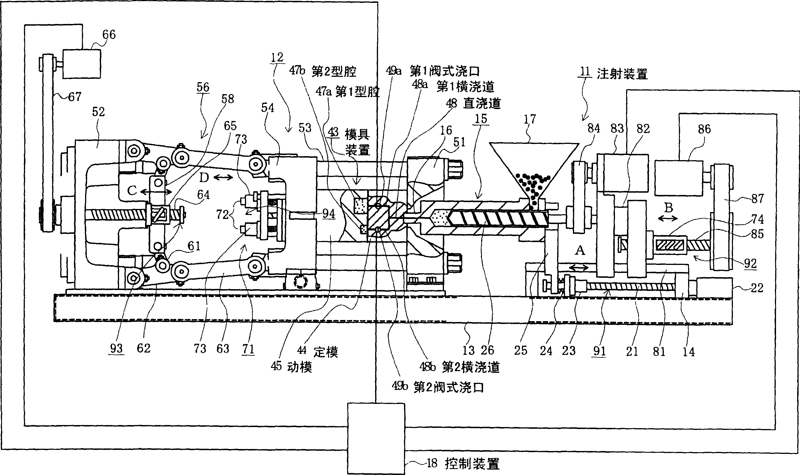
[0079] figure 1 It is a schematic diagram of an injection molding machine according to a first embodiment of the present invention.

[0080] In the figure, 11 is an injection device, 12 is a mold clamping device arranged opposite to the injection device 11, 13 is a molding machine frame supporting the injection device 11 and the mold clamping device 12, 14 is supported by the molding machine frame 13, and An injection device frame supporting the injection device 11 , 81 is a guide rail arranged along the longitudinal direction of the injection device frame 14 , and 43 is a mold device composed of a fixed mold 44 and a movable mold 45 . A first cavity 47 a and a second cavity 47 b are formed as a plurality of cavities in the mold device 43 .

[0081] In addition, a ball screw shaft 21 is rotatably supported by the injection device frame 14 , and one end of the ball ...


PUM


Abstract

An object is to charge resin into cavities in accordance with molding conditions individually set for the cavities by controlling valve gates disposed within a mold apparatus or a mold support apparatus by use of a controller, to produce individual molded products under optimal molding conditions, to produce molded products having no variation in molding accuracy and quality, and to lower the cost of the mold apparatus. For such a purpose, an injection molding machine includes a plurality of cavities formed in a mold apparatus; resin passages for charging resin into the cavities; a plurality of selection means respectively disposed in the resin passages corresponding to the cavities and adapted to selectively open and close the corresponding resin passages; and a controller for controlling the selection means.

Description

technical field [0001] The present invention relates to injection molding machines. Background technique [0002] Conventionally, in an injection molding machine, a screw is advanced in a heating cylinder, heated and melted resin is injected and filled into a cavity of a mold device under high pressure, and the resin is cooled and solidified in the cavity to form a molded product. . Furthermore, in order to improve the productivity of the injection molding machine, double-cavity or multi-cavity molding capable of molding a plurality of molded products in one cycle of molding steps is performed (see, for example, Patent Documents 1 and 2). [0003] At this time, a plurality of cavities are formed in the mold device, and the injected resin is distributed and filled into the plurality of cavities through the sprue and the runner. Therefore, a plurality of molded products can be molded simultaneously in one cycle of the molding process, and the productivity of the injection mo...

Claims


Application Information

Patent Timeline
Patent Type & Authority Applications(China)
IPC IPC(8): B29C45/28B29C45/76
Inventor 葛见俊之
Owner SUMITOMO HEAVY IND LTD
Why Eureka
Try Eureka