Apparatus and method for displaying a holographic video image sequence

A technology for video images and images, which is applied to equipment and fields for displaying holographic video image sequences, can solve problems such as inability to use real-time applications and insufficient image quality for display applications, and achieve improved noise reduction technology and improved display efficiency. , the effect of small light loss

Active Publication Date: 2007-02-21
CAMBRIDGE ENTERPRISE LTD
View PDF1 Cites 9 Cited by
  • Summary
  • Abstract
  • Description
  • Claims
  • Application Information

AI Technical Summary

Problems solved by technology

However, the computational complexity of current holographic generation algorithms prevents them from being used in real-time applications
A

Method used


Image

  • Apparatus and method for displaying a holographic video image sequence
  • Apparatus and method for displaying a holographic video image sequence
  • Apparatus and method for displaying a holographic video image sequence

Examples


Example Embodiment

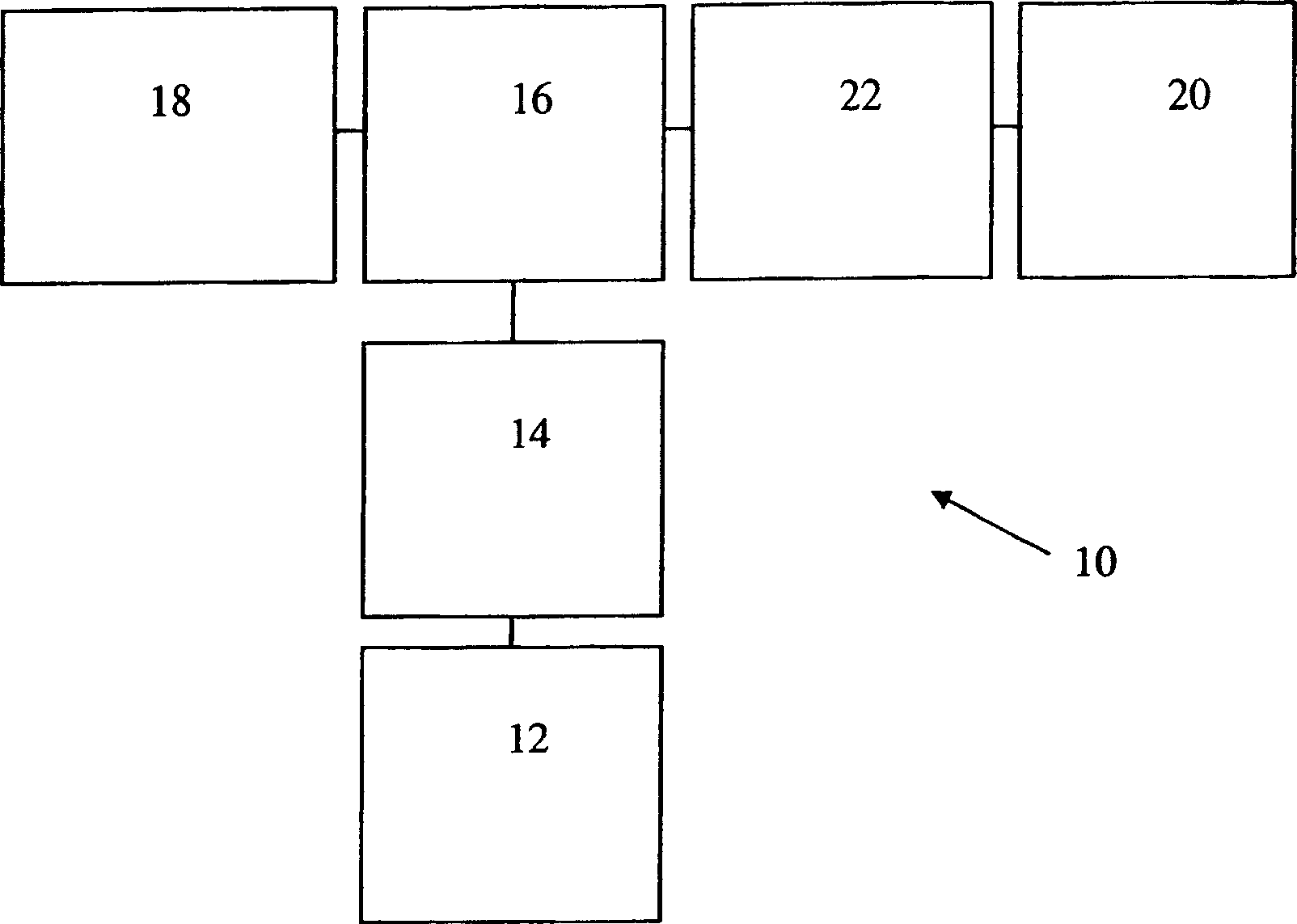
[0021] In the following description, the same reference numerals are used in the respective drawings to denote the same components.

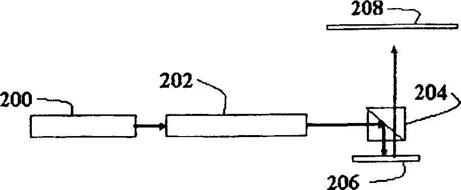
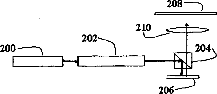
[0022] In general, the present application relates to a device for projecting video images from a pure phase hologram (commonly known as an axiogram) generated by a computer. The correlation diagrams must be able to be quickly reconstructed so that they can be displayed on a pixelated liquid crystal on silicon (LCOS) spatial light modulator, which has been configured to operate effectively as a pure phase modulator. The LCOS pure phase SLM is illuminated by an appropriately expanded light beam from a partially coherent light source (such as a laser or superluminescent diode, LED), and the pure phase correlation image is converted into a real intensity image in the far field. ). A projection lens can be used to make the far field closer for Fourier transform. By using fast hardware-based processors (such as FFT, FPGA, and DS processors), and by using...


PUM


Abstract

A method of displaying a video image comprises receiving sequential image frames at a processor. Each image frame is processed to obtain a kinoform. A programmable diffractive element such as an SLM represents the sequence of kinoforns allowing reproduction of the image using a suitable illumination beam.

Description

technical field [0001] The present invention relates to a device and a method for displaying video images, for example using holography. Background technique [0002] Various devices are known for displaying images using holography, for example using computer holography (CGH). One of these known devices is described in US6437919, in which an electrically addressable spatial light modulator (SLM) is addressed to provide a 3D holographic representation of an image. Thus, when the SLM is illuminated by a suitable illumination source, the image is reconstructed in the playback field (RPF). [0003] The problem with existing projection displays, such as holographic displays, is that light efficiency is low, and 3D displays require a large number of pixels. [0004] Furthermore, holographically generated 2D video images are known to have significant advantages over conventional projected video images, especially in terms of clarity and efficiency. However, the computational com...

Claims


Application Information

Patent Timeline
IPC IPC(8): G03H1/08G03H1/22G03H1/32
CPCG03H1/2294G03H2001/2218G03H1/2249G03H1/2205G03H2001/306G03H2001/261G03H2226/02G03H1/0841G03H2225/55G03H2225/32G03H2240/41G03H2225/60G03H2222/35G03H2001/0816G03H2225/25G03H2001/2215G03H2225/31G03H2225/52G03H2210/30G03H2223/55G03H2210/20G03H1/0808G03H2001/085G03H2240/51G03H2001/2297G03H2210/40G03H2240/42G03H2210/454G03H2001/2231G03H2223/13G03H2001/2271G03H2001/2255G03H1/08G03H2225/61G03H1/2286G03H1/00G03H1/22G03H1/2645
Inventor 威廉·克罗斯兰尼尔·科林斯爱德华·巴克利阿德里安·凯布尔尼古拉斯·劳伦斯彼得·马什蒂莫西·威尔金森
Owner CAMBRIDGE ENTERPRISE LTD
Why Eureka
Try Eureka