Backlight deviced and control method thereof

A backlight device and backlight control technology, applied in lighting devices, lighting device parts, optics, etc., can solve the problems of large size and difficult to set backlight units, etc.

Inactive Publication Date: 2007-02-28
PHICOM CORP
View PDF0 Cites 15 Cited by
  • Summary
  • Abstract
  • Description
  • Claims
  • Application Information

AI Technical Summary

Problems solved by technology

However, it is not easy to set on the backlight unit due to its still heat problem and its large size

Method used


Image

  • Backlight deviced and control method thereof
  • Backlight deviced and control method thereof
  • Backlight deviced and control method thereof

Examples


Embodiment Construction

[0040] Next, preferred embodiments of the present invention will be described in detail with reference to the drawings.

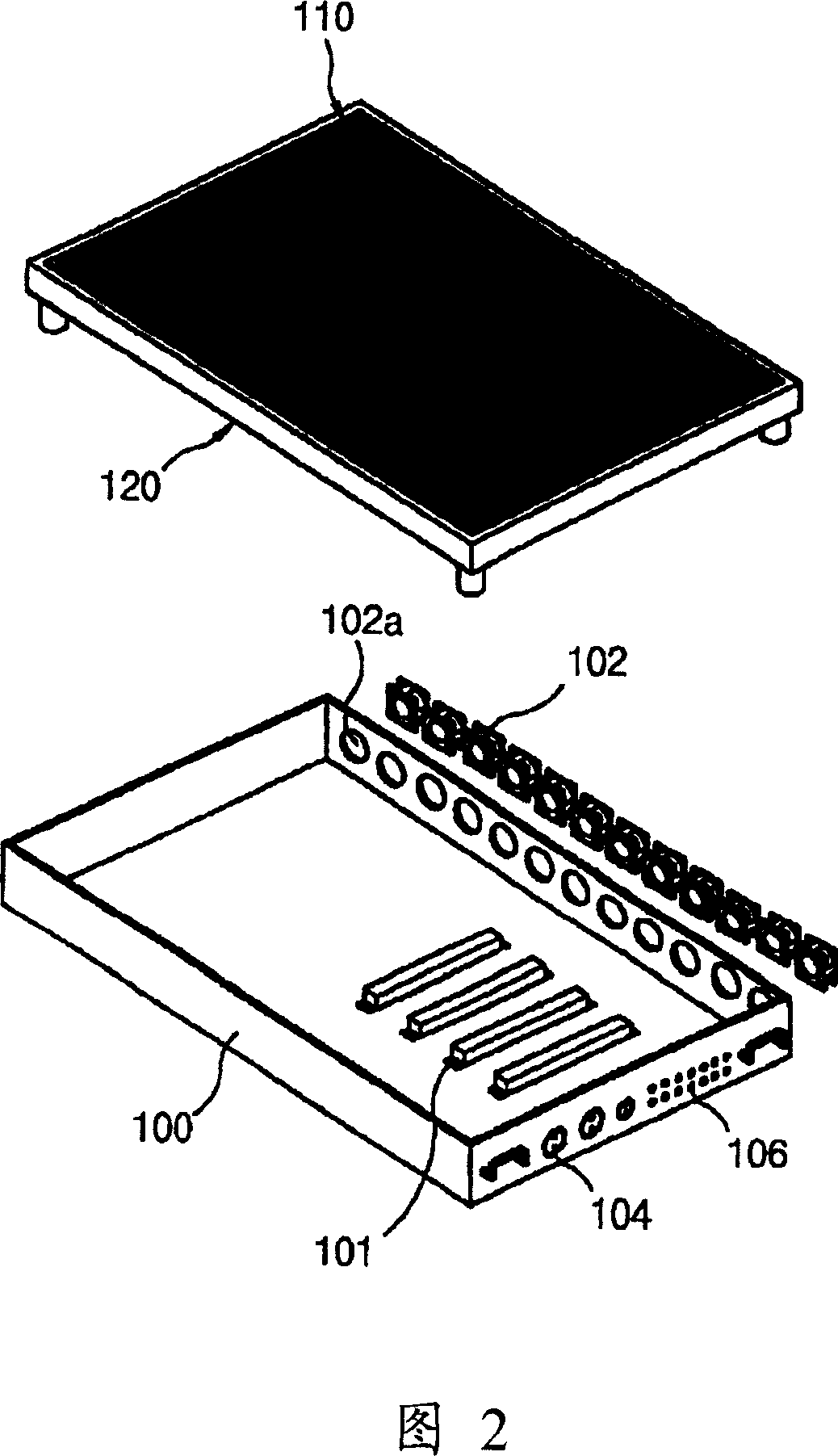
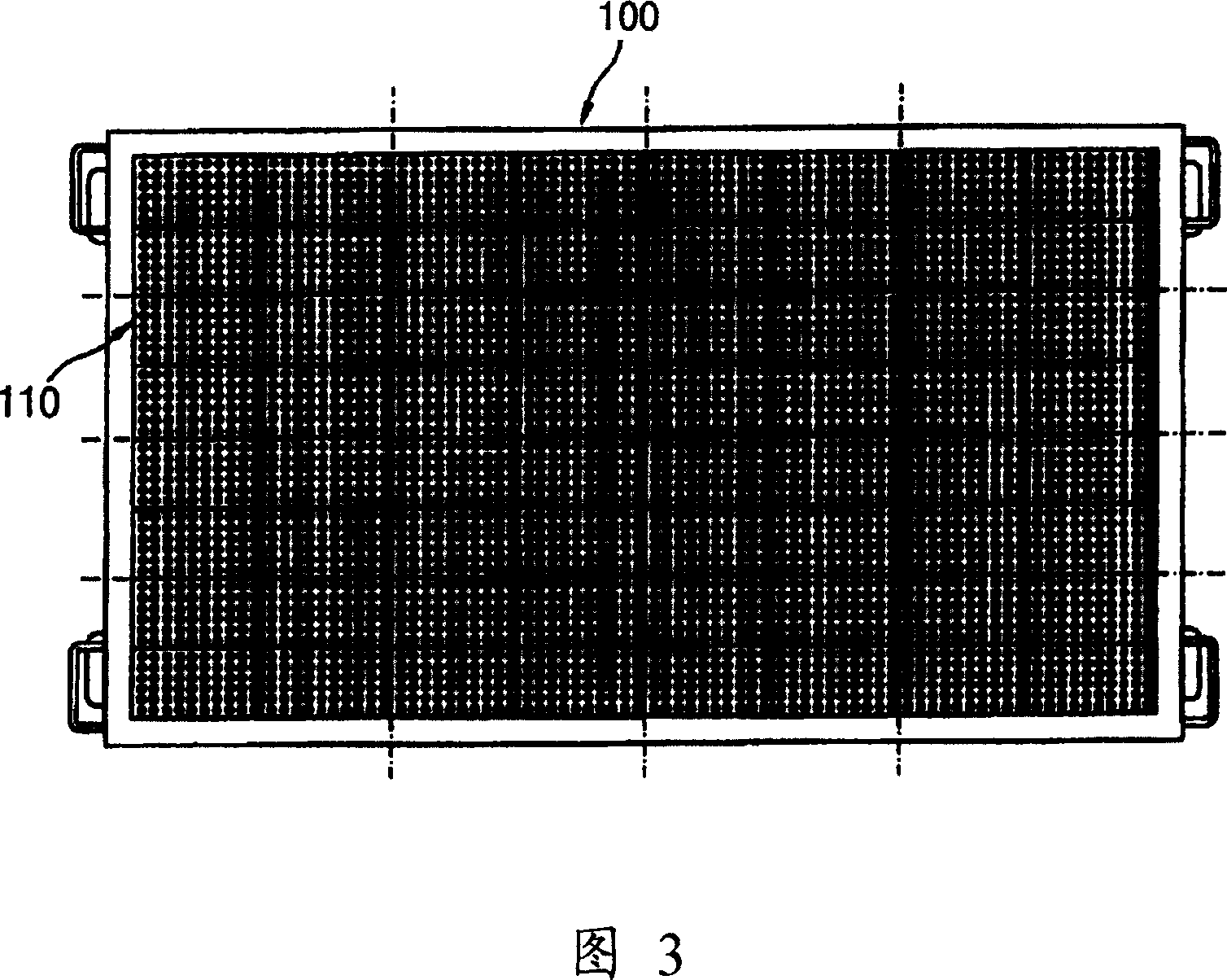
[0041] FIG. 2 is an exploded perspective view of the backlight device of the present invention. FIG. 3 is an assembled front view of the backlight device of the present invention. FIG. 4 is a side view of FIG. 3 . Fig. 5 is a first embodiment of an assembled state of the LED unit and the substrate. FIG. 6 is an enlarged perspective view of part A of FIG. 5 . 7 is a perspective view of an assembled state of an LED unit and a substrate according to a second embodiment of the present invention. FIG. 8 is an enlarged perspective view of part B of FIG. 7 . FIG. 9 is an enlarged perspective view of part C in FIG. 7 . 10 is a perspective view of an assembled state of an LED unit and a substrate according to a third embodiment of the present invention. FIG. 11 is an enlarged perspective view of part D in FIG. 10 . FIG. 12 is a flow chart of the backlight con...


PUM


Abstract

The present invention relates to a backlight device and control method thereof, including a case (100); a base substrate (120) installed inside the case (100), and a plurality of LED units (110) modularized and mounted on the base plate (120). In case a part of the plurality of LED units mounted on the base plate is in trouble, a local replacement of an LED unit is possible, so the repair and maintenance are simple and time consuming is short. Further, each of the plurality of modularized LED units is individually controlled in brightness. Therefore, brightness is uniformized among the plurality of LED units to advance the detection precision and the product reliability. In the modularized LED units which can be controlled respectively, the LED units arranged on the substrate fringe have higher brightness, so the brightness deviation is reduced. In addition, the LED units are small in themselves so a plurality of LED units are adjacently arranged to reduce the brightness deviation. Further, a reflecting plate is disposed integrally on the massive substrate of a plurality of LED units of the arranged units, which can simplify the component parts.

Description

technical field [0001] The present invention relates to a backlight device and its control method of liquid crystal panel illumination detection equipment, more specifically, to a backlight device which is easy to maintain and eliminates the uneven brightness of each LED unit and its control method. Background technique [0002] A liquid crystal display (Liquid Crystal Display: LCD) device is usually disposed inside the LCD panel, and is provided with a driving circuit operated by a microprocessor to display images on the LCD panel. [0003] On the other hand, in the manufacturing process of the LCD panel, illumination inspection is performed at the final stage. This LCD panel illumination detection device uses a detection device to respectively send electrical signals to the data lines and gate lines of the LCD panel to drive the driving circuit of the LCD panel. In addition, since the liquid crystal display itself cannot emit light for displaying images, a light source mu...

Claims


Application Information

Patent Timeline
Patent Type & Authority Applications(China)
IPC IPC(8): G02F1/13357G02F1/133G09G3/34G02F1/1335F21S2/00F21V23/00F21V23/04F21Y101/02H01L33/48
CPCG02F1/133603G02F1/133608G02F1/133611G02F1/133314
Inventor 崔英民
Owner PHICOM CORP
Why Eureka
Try Eureka