Power cord chopped wave communication transmitting-receiving circuit

A technology of communication transceiver and power line, which is applied in the direction of distribution line transmission system, etc., can solve the problems of increased performance requirements of power supply and receiving equipment, limitations of transmission distance and transmission speed, and limited number of nodes on the bus, achieving simple structure, The effect of saving length and more nodes can be attached

Inactive Publication Date: 2007-02-28
ZHEJIANG UNIV
View PDF0 Cites 17 Cited by
  • Summary
  • Abstract
  • Description
  • Claims
  • Application Information

AI Technical Summary

Problems solved by technology

This method has the following disadvantages: 1. Increased cost; 2. Limited transmission distance and transmission speed; 3

Method used


Image

  • Power cord chopped wave communication transmitting-receiving circuit
  • Power cord chopped wave communication transmitting-receiving circuit

Examples


Example Embodiment

[0011] Specific implementation method

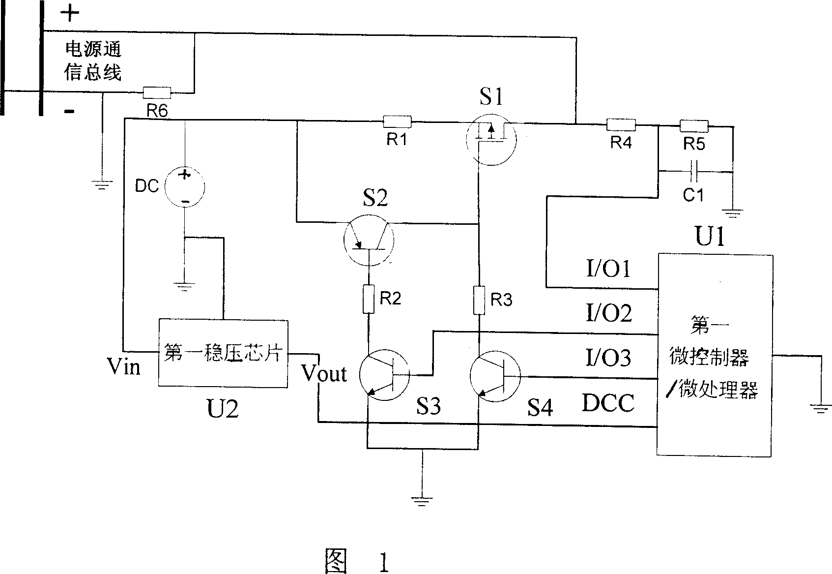
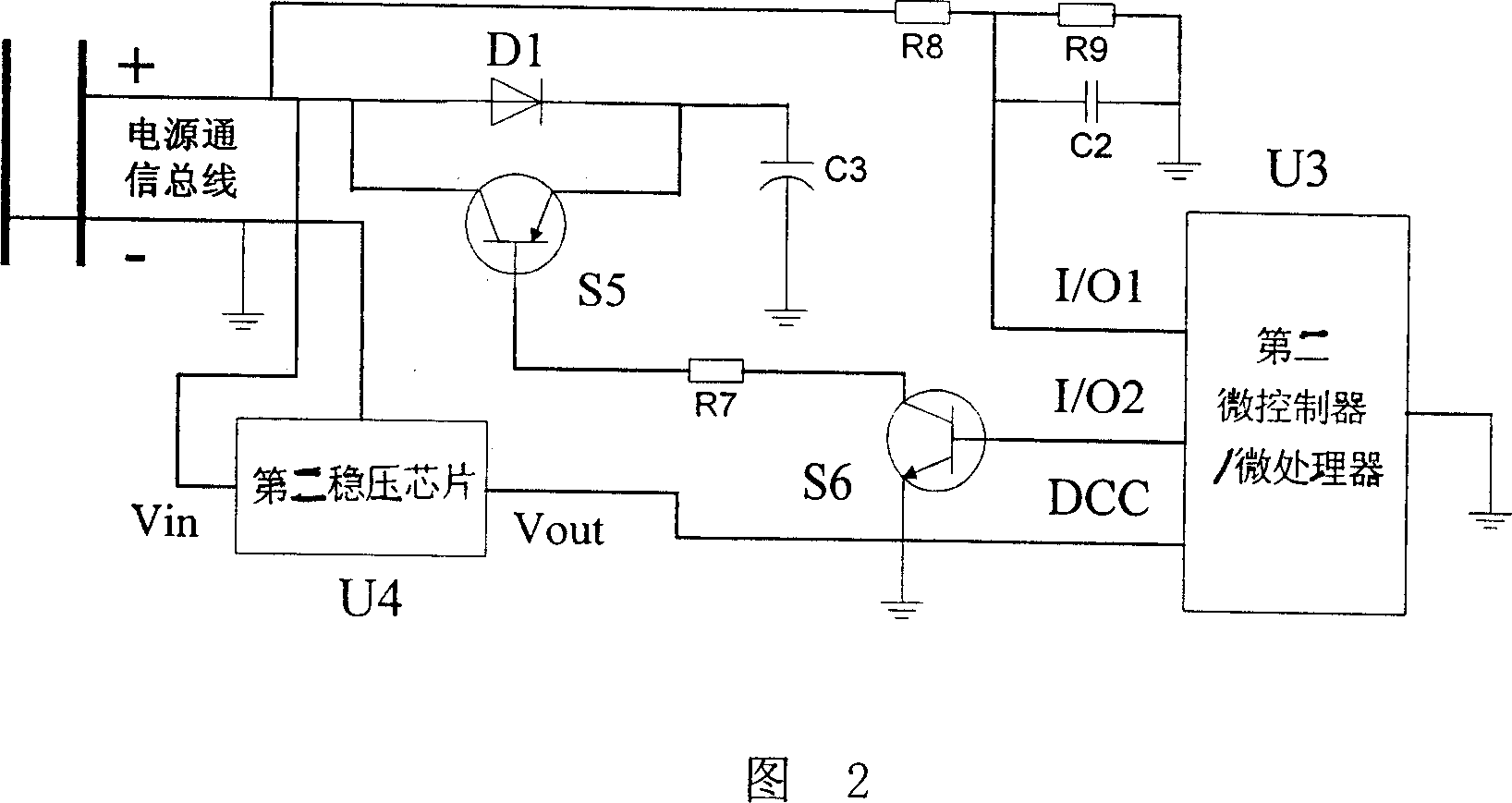
[0012] The power line chopper communication transceiver circuit of the present invention includes two parts: a host circuit and a slave circuit. The host circuit is shown in FIG. 1, and includes a first microcontroller / microprocessor U1, composed of a field effect transistor S1 and a first triode S2. , The second triode S3, the third triode S4 constitute the electronic switch logic circuit, the direct current power supply DC, the first voltage regulator chip U2 and resistor, the second triode S3 and the third triode S4 base Connected to the two output pins I / O2 and I / O3 of the first microcontroller / microprocessor U1 respectively, the emitters of the second transistor S3 and the third transistor S4 are grounded, and the third transistor The collector of the tube S4 is connected to one end of the third resistor R3. The other end of the third resistor R3 is connected to the collector of the first transistor S2 and the gate of the field effect t...


PUM


Abstract

The invention relates to a power wire communication receiving/sending circuit, which comprises host circuit and sub circuit. Wherein, the electric switch logic circuit of host circuit controls the electric switch to modulate the digit signal into switch impulse to be sent to the power wire, to use two different impulse widths to represent 0 and 1 signals; then the sub circuit receives said impulse signal, at the sending slot of host circuit, to use microcontroller/microprocessor of sub circuit to control the electric switch logic circuit to layer feedback 0 or 1 signals at the low voltage sent from host circuit, to complete the communication of power bus. The invention has simple structure and can realize power supply and signal communication at one couple of wires, to reduce the complexity of logic wire, with less voltage consumption and high communication quality.

Description

technical field [0001] The invention relates to a circuit for simultaneous transmission of a low-voltage DC power supply line and a data signal line, which belongs to the field of communication and field bus transmission. Background technique [0002] In the fields of industrial control, intelligent buildings, equipment monitoring, etc., there is a large demand for connecting scattered detection points and control points on the site through bus technology. Currently commonly used bus technologies are RS485, CAN, ProfiBus and so on. Compared with the centralized star connection, the bus mode can greatly reduce the total length of the connection and the complexity of wiring. The interface of each bus module requires only two pairs of wires: a pair of power wires and a pair of signal wires. [0003] In order to further reduce the connection, there is also a technology that simultaneously transmits signals and power through a pair of wires. These technologies generally adopt ...

Claims


Application Information

Patent Timeline
IPC IPC(8): H04B3/54
Inventor 吴建德何湘宁
Owner ZHEJIANG UNIV
Why Eureka
Try Eureka