Constant velocity universal joint

A constant velocity universal joint and track technology, applied in the field of universal joints, can solve problems such as cost increase, unpredictable enhancement of the torsional stiffness of the connecting shaft, etc., and achieve the effects of reducing swing, improving NVH characteristics, and increasing design flexibility

Inactive Publication Date: 2007-02-28
NTN CORP
View PDF0 Cites 3 Cited by
  • Summary
  • Abstract
  • Description
  • Claims
  • Application Information

AI Technical Summary

Problems solved by technology

But the additional damper causes an increase in cost
In addition, although the frequency can be adjusted, it cannot be expected to enhance the torsional rigidity of the connecting shaft

Method used


Image

  • Constant velocity universal joint
  • Constant velocity universal joint
  • Constant velocity universal joint

Examples


Embodiment Construction

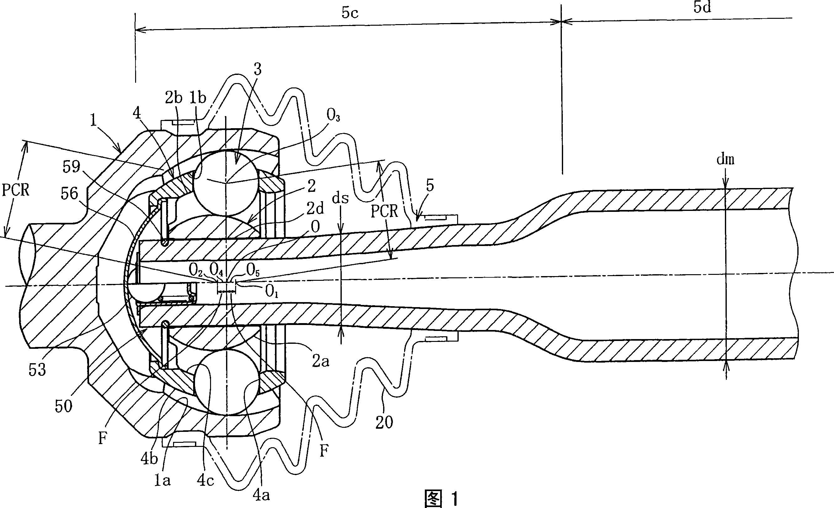
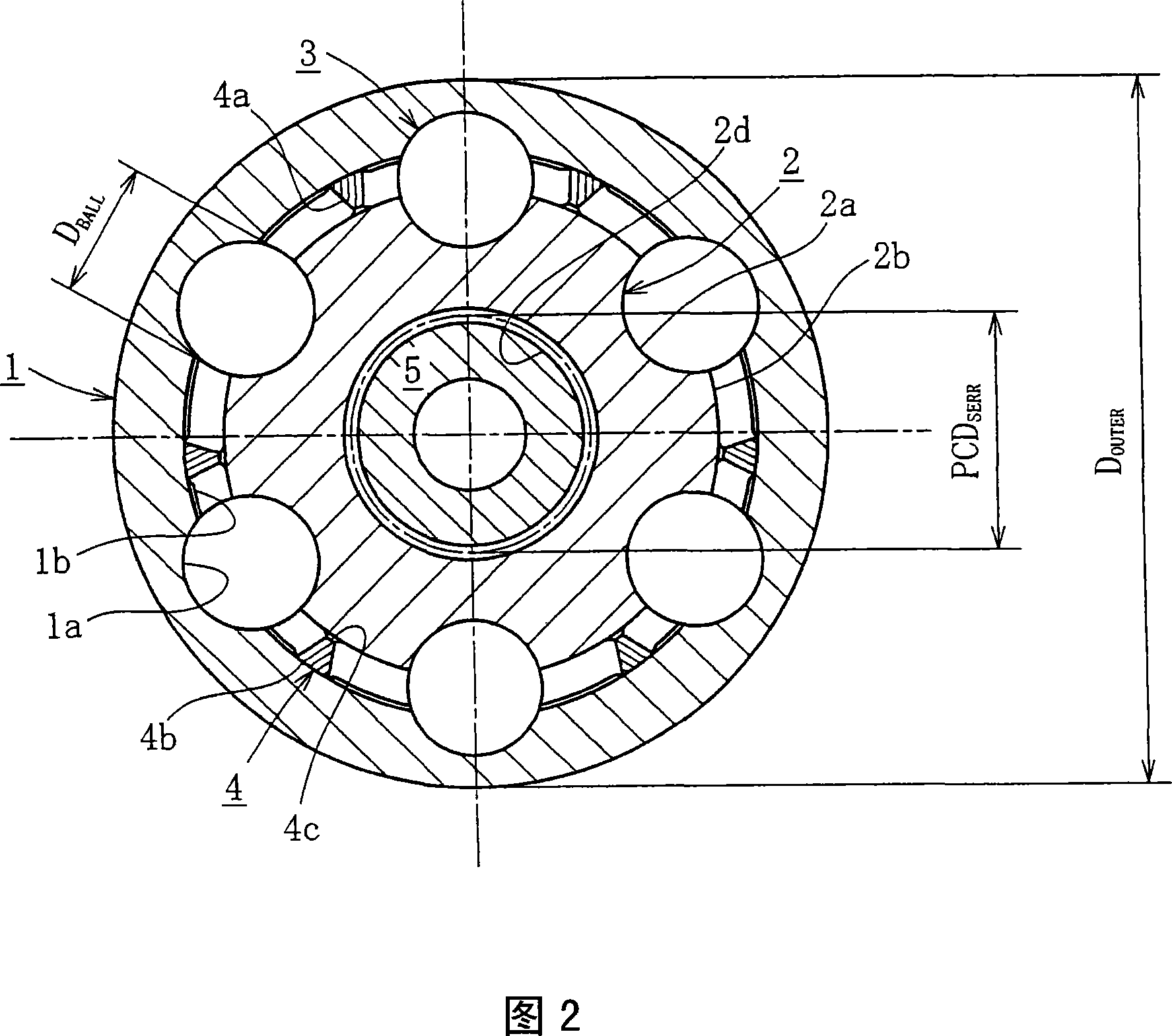
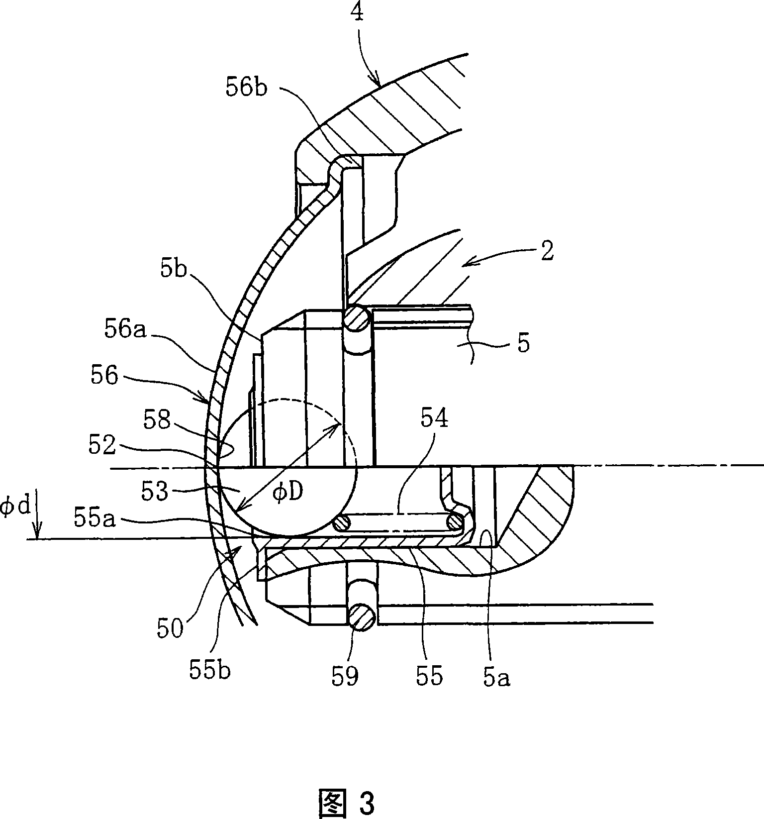
[0023] The embodiments of the constant velocity joint according to the present invention will be explained in detail below. The embodiments described below take as an example the application of the present invention to a ball and cage type constant velocity joint (BJ) which is one of the fixed type constant velocity joints. However, the present invention is not limited to this, and can also be applied to undercut free-type (UJ). The constant velocity universal joint according to the present invention can be used not only for steering but also for drive shafts or transmission shafts.

[0024] First, the steering device in which the fixed type constant velocity joint is installed will be briefly explained. As shown in Figures 5(a) to 5(c), in order to convert the rotational movement of the steering wheel (steering wheel) into the reciprocating movement of the tie rod 69, the steering device is passed by one or more steering The steering column constituted by the shaft 62 transmits t...


PUM


Abstract

The present invention aims to achieve the high rigidity and light weight of a connecting shaft of a constant velocity universal joint, and to reduce manufacturing costs. A hollow connecting shaft 5 is provided with an axial end section 5c having teeth 5c which are engaged with an engagement section 2d of an inner member 2, and a middle section 5d continued from the axial end section 5c. To mold the connecting shaft 5, both end sections of a pipe material with an outside diameter dm are drawn, and then the teeth (splines or serrations) 5c are molded in the outer periphery of the drawing-molded axial end section 5c on an axial end side by form rolling or the like. The outside diameter of the axial end section 5c is ds, and the outside diameter of the middle section 5d is dm as with that of the pipe material (ds < dm).

Description

Technical field [0001] The present invention relates to a constant velocity universal joint in which a hollow connecting shaft is connected to a joint part of an inner part. More specifically, the present invention relates to a steering wheel and a propeller shaft suitable for automobiles. Or the universal joint of the drive shaft. Background technique [0002] Constant velocity universal joints are broadly divided into fixed type and sliding type, wherein the fixed type only allows angular displacement between two shafts and the sliding type allows angular displacement and axial displacement, and each type is based on the work Conditions, applications, and similar conditions are selected. The Rzeppa-type constant velocity joint (ball fixed joint) is a typical fixed type, and the double offset-type constant velocity joint is a typical Sliding type. [0003] The aforementioned constant velocity universal joints are widely used in automobile transmissions, for example, to connect t...

Claims


Application Information

Patent Timeline
Patent Type & Authority Applications(China)
IPC IPC(8): F16D3/20F16D3/22F16C3/02B62D1/20F16D1/06
CPCF16D2001/103F16D3/223F16D2003/2232F16D3/2245F16D1/06
Inventor 石岛实山崎健太
Owner NTN CORP
Why Eureka
Try Eureka