AI technical title is built by Patsnap AI team. It summarizes the technical point description of the patent document.
A lens barrel and lens technology, which can be used in image communication, installation, instruments, etc., and can solve the problems of occupying space and unfavorable lens barrel miniaturization.
Inactive Publication Date: 2007-02-28
SONY CORP
View PDF1 Cites 7 Cited by
Summary
Abstract
Description
Claims
Application Information
AI Technical Summary
This helps you quickly interpret patents by identifying the three key elements:
Problems solved by technology
Method used
Benefits of technology
Problems solved by technology
However, since the idling portion occupies space in the direction of the optical axis, it is not conducive to miniaturization of the lens barrel.
[0007] In addition, sensors such as the detection sheet of the movable lens and the photo interrupter also take up space, which is not conducive to the miniaturization of the lens barrel.
Method used
Image
Click on the blue label to locate the original text in one second.
Reading with bidirectional positioning of images and text.
Examples
Embodiment 1
[0025] Next, Embodiment 1 of the present invention will be described with reference to the drawings.
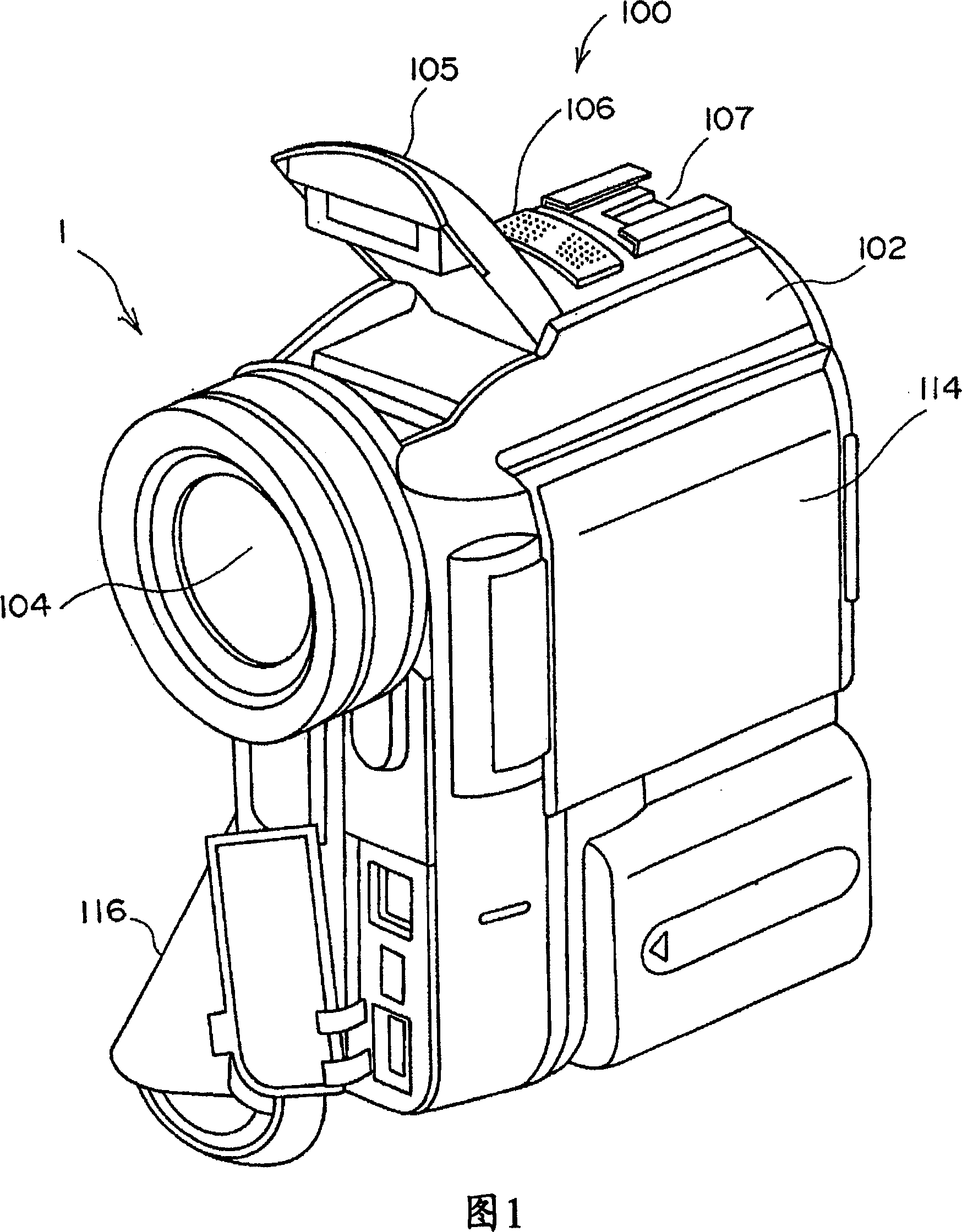
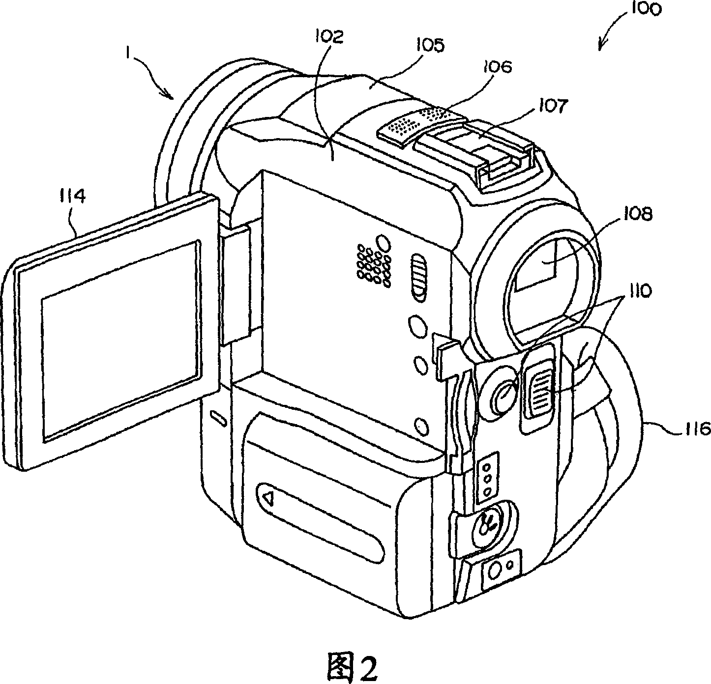
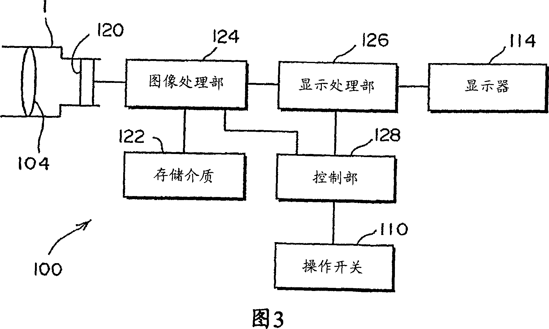
[0026] 1 is a front perspective view of the image capture device of Embodiment 1, FIG. 2 is a rear perspective view of the image capture device, and FIG. 3 is a structural block diagram of the image capture device.
[0027] As shown in FIGS. 1 and 2 , the image capture device 100 of this embodiment is a video camera, which includes a casing 102 as a casing.
[0028] The upper front surface of the housing 102 is provided with a lens barrel 1 for accommodating and maintaining the photographic optical system 104, and a flashlight unit 105 is provided in sequence from the front of the upper surface of the housing 102 to the rear of the upper surface, and a camera for recording sound. The microphone 106, and the slide rail 107 for installing accessories, the flash unit 105 emits auxiliary light when shooting, and can automatically pop up / reset.
[0122] The difference between Embodiment 2 and Embodiment 1 is that the photographing optical system is a contraction lens.
[0123] Fig. 9 is a cross-sectional view of a shrinking lens, (a) is a contracted state, (b) is a wide-angle state, (c) is a long-distance state, and Fig. 10 is a cross-sectional view of a movable lens. In addition, in FIG. 9 and FIG. 10 , the same parts or components as in the first embodiment are given the same reference numerals, and detailed description thereof will be omitted.
[0124] As shown in Figure 9, the photographic optical system contained in the lens barrel 1 adopts a third lens group structure, that is, includes: a first lens group 50, a second lens group 52, and a third lens group arranged in sequence from the front to the rear 54.
[0125] The lens barrel 1 drives the first lens group 50 and the second lens group 52 in the direction of the optical axis along a predetermined cam curve thro...
PUM
Abstract
A lens barrel and an imaging apparatus advantageous in enhancing the feeding accuracy of a movable lens and in reducing the size of the barrel. A position detecting means (34) for two groups generating positional data corresponding to the position of a two-group lens (12) along the optical axis is provided. The amount of rotation of a motor (2804) for two groups is controlled according to the positional data fed from the position detecting means (34) such that the position of the two group lens (12) along the optical axis agrees with a target position. If the positional data is invariant for a specified time during the rotation of the motor (2804), it is judged that movement of the two-group lens (12) is stopped forcedly and the rotation of the motor (2804) is stopped immediately.
Description
technical field [0001] The invention relates to a lens barrel and an image capture device. Background technique [0002] Image capture devices such as digital still cameras or digital video cameras include lens barrels that assemble photographic optics within the barrel. [0003] This lens barrel includes: for example, a movable lens arranged in the lens barrel, movable in the direction of its optical axis, but unable to rotate around the optical axis; and a drive for moving the movable lens in the direction of the optical axis. mechanism, the driving mechanism includes: an internal thread provided on the movable lens; an external thread component screwed with the internal thread and extending in a direction parallel to the optical axis direction; the external thread A motor for rotating the member; and a urging unit composed of a coil spring for urging the movable lens from the longitudinal direction of the externally threaded member (for example, refer to JP-A-2002-287002...
Claims
Application Information
Patent Timeline
Application Date:The date an application was filed.
Publication Date:The date a patent or application was officially published.
First Publication Date:The earliest publication date of a patent with the same application number.
Issue Date:Publication date of the patent grant document.
PCT Entry Date:The Entry date of PCT National Phase.
Estimated Expiry Date:The statutory expiry date of a patent right according to the Patent Law, and it is the longest term of protection that the patent right can achieve without the termination of the patent right due to other reasons(Term extension factor has been taken into account ).
Invalid Date:Actual expiry date is based on effective date or publication date of legal transaction data of invalid patent.

