Light source device and video image displaying apparatus using the same

A light source device and optical axis technology, which is applied in the cooling/heating device of the lighting device, the parts of the lighting device, the electric light source, etc., and can solve the problem of reduced light collection efficiency, failure to reach the focus point, area, and reduction of collection efficiency, etc. problem, to achieve the effect of small imaging magnification, good small light spot, and improved light-gathering efficiency

Inactive Publication Date: 2007-02-28
SHARP KK
View PDF3 Cites 11 Cited by
  • Summary
  • Abstract
  • Description
  • Claims
  • Application Information

AI Technical Summary

Problems solved by technology

[0033] However, in the optical axis perpendicular arrangement type light source device shown as the first prior art, when the reflective surface of the reflector is formed as an aspheric surface such as an elliptical surface or a hyperboloid surface, there is no light emitted from the arc tube. Components irradiated on the aspheric reflective surface of the reflector cannot reach the desired focusing point or area, reducing the light collection efficiency
[0034] In addition, in the optical axis perpendicular arrangement type light source device shown as the second prior art, the reflective surface of the reflector behind the arc tube is formed as a concentric circular surface when viewed from the optical axis, and the reflective surface is formed as a concentric circular surface when viewed from the optical axis. In the case where a light-condensing element such as a lens is arranged in front of the light-emitting tube, when the light-emitting light from the light-emitting tube and the reflective surface formed as the concentric circular surface is collected by the light-condensing element, the collection angle of the light is limited. Therefore, In this case, there will also be a problem that the light collection efficiency will decrease.

Method used


Image

  • Light source device and video image displaying apparatus using the same
  • Light source device and video image displaying apparatus using the same
  • Light source device and video image displaying apparatus using the same

Examples


Embodiment Construction

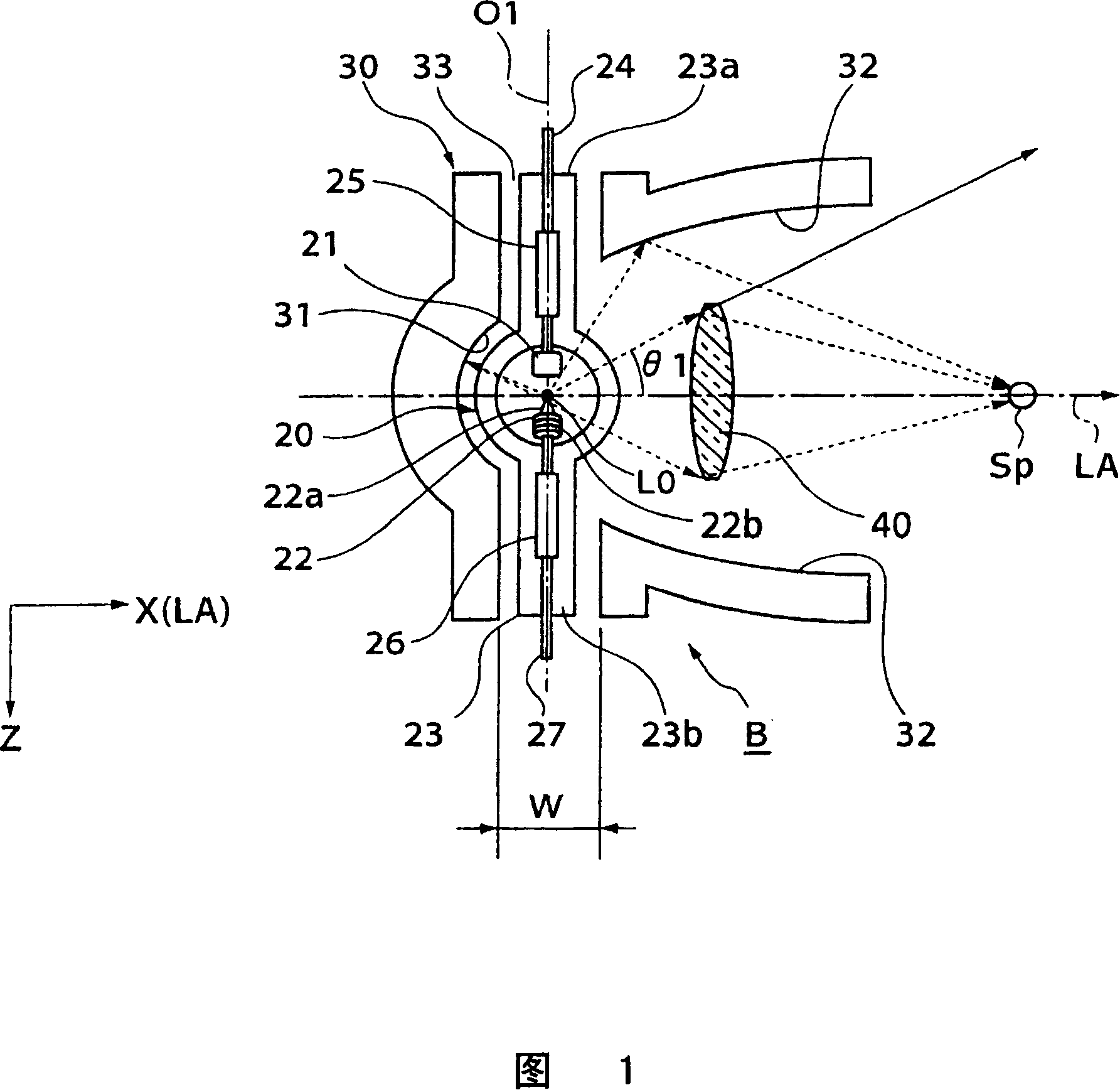
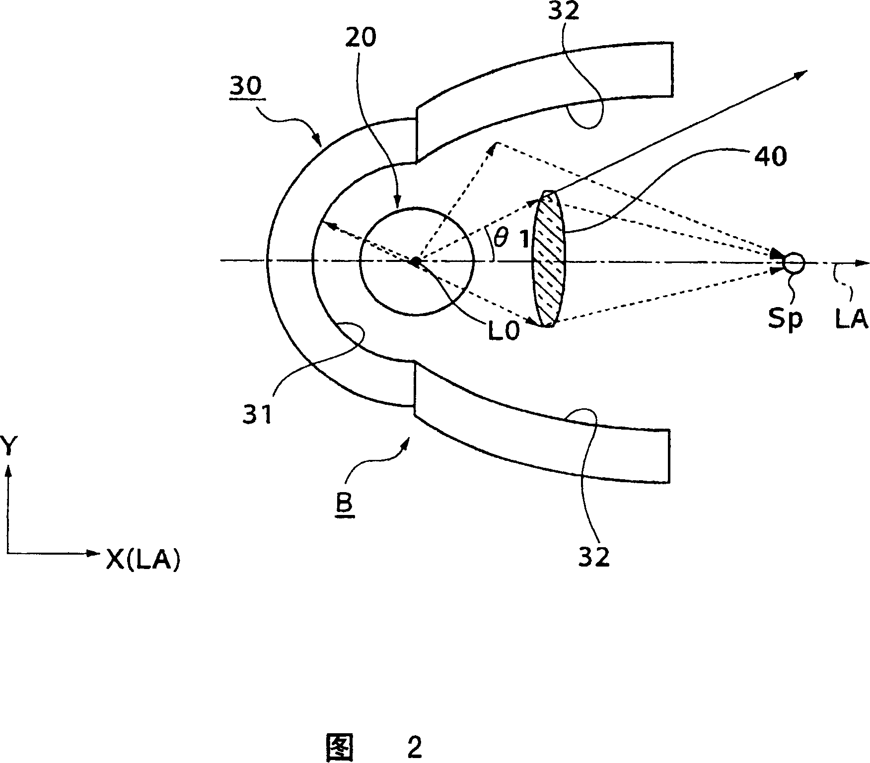
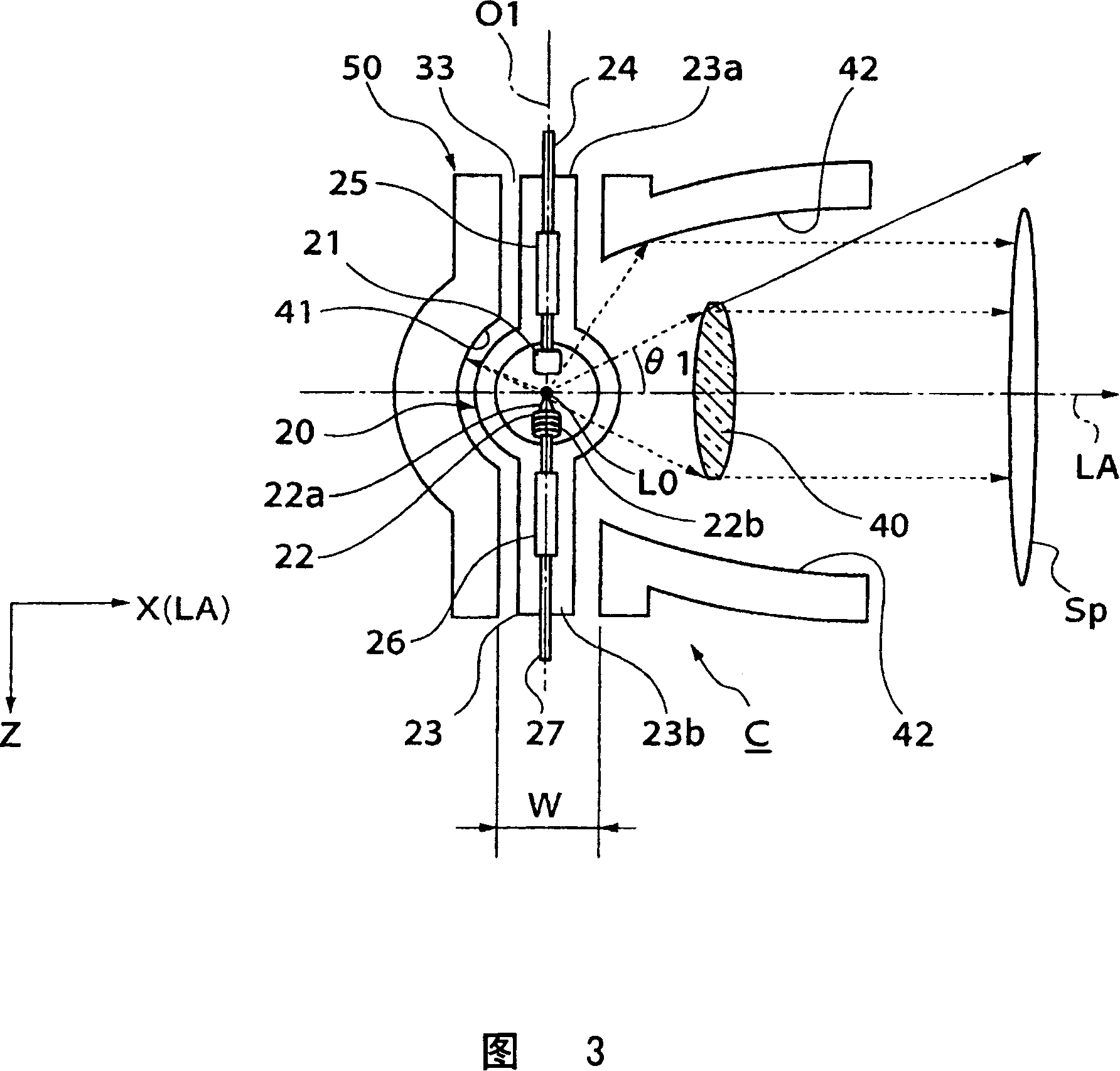
[0078] Next, an embodiment of the present invention will be described with reference to FIGS. 1 to 16 . First, a light source device according to a first embodiment of the present invention will be described with reference to FIGS. 1 and 2 . FIG. 1 is a horizontal sectional view showing the basic structure of a light source device according to a first embodiment of the present invention, and FIG. 2 is a side sectional view of the light source device.

[0079] As shown in FIG. 1 , the light source device B according to the first embodiment of the present invention includes: an arc tube 20 as a light source; a reflector 30 for reflecting light emitted from the arc tube 20 ; and a condenser 40 .

[0080] The arc tube 20 forms the same structure as the aforementioned arc tube 1, which will be described in more detail below.

[0081] The arc tube 20 is a direct current lighting high-pressure mercury lamp with a diameter of about 10 (mm), and an anode electrode 21 and a cathode ele...


PUM


Abstract

A light source apparatus having, in spite of its simple and compact construction, enhanced efficiency of condensing light in a predetermined small diameter region. The light source apparatus has a light emitting tube (20) with a pair of main electrodes (21, 22) and has a reflector (30) for reflecting light emitted from the light emitting tube (20). The electrode axis O1 of the main electrodes (21, 22) intersects with the optical axis LA of the emitted light. In the reflector (30) are formed a first reflector section (31) and a second reflector section (32). The first reflector section (31) has a spherical surface with its center at a light emitting point L0 of the light emitting tube (20), and the second reflector section (32) has a curved surface different from that of the first reflector section (31). The reflector (30) also has a light condensing body (40) for condensing light that is emitted from the light emitting tube (20) to places other than the second reflector section (32) and irradiating the condensed light to a predetermined direction or region.

Description

technical field [0001] The present invention relates to a light source device having a reflection mirror for reflecting light emitted from a light emitting tube, and an image display device using the light source device. Background technique [0002] The background art of the present invention will be described with reference to FIGS. 17 to 23 . Fig. 17 (a), (b) is a comparative explanatory diagram of the arrangement direction of the luminous tubes, Fig. 18 is a horizontal cross-sectional view showing the schematic structure of the optical axis parallel arrangement type light source device, and Fig. 19 is a view showing the light source shown in Fig. Horizontal cross-sectional view of the state of the emitted light emitted from the light-emitting point of the axis-parallel-arranged light source device. [0003] Conventionally, arc tubes such as metal halide lamps, xenon short-arc lamps, and high-pressure mercury lamps that emit light by arc discharge have been used as light...

Claims


Application Information

Patent Timeline
Patent Type & Authority Applications(China)
IPC IPC(8): G03B21/20F21S2/00F21V7/09F21V7/10F21V13/00F21V29/00G02B5/10F21V13/04G03B21/14H04N5/74
CPCG02B5/10F21V13/04H04N5/74F21V7/09G03B21/00G03B21/14
Inventor 京本忠男斋藤荣武田昭信
Owner SHARP KK
Why Eureka
Try Eureka