Cogeneration device for light condensation of single-reflection compound parabolic condenser and application method

A compound paraboloid and combined heat and power technology, which is applied in the research field of comprehensive utilization of concentrated photovoltaic light and heat, can solve the problems of poor wind resistance, excessive materials, and insufficient rigidity, and achieve the effect of low cost and high concentration efficiency

Active Publication Date: 2015-11-04
XI AN JIAOTONG UNIV
View PDF5 Cites 4 Cited by
  • Summary
  • Abstract
  • Description
  • Claims
  • Application Information

AI Technical Summary

Problems solved by technology

[0002] For concentrators for comprehensive utilization of photovoltaic light and heat, trough, dish, spherical concentrating and Fresnel concentrating technologies are mainly used at present, and these concentrating technologies cannot use the scattered light of the sun; Concentrators, because their focusing planes are on the upper side of the mirror surface, the photovoltaic cell components or heat collectors installed at the focal plane will block part of the incident sunlight, thereby reducing the utilization rate of solar energy. In addition, the photovoltaic cell components or collectors The heater is suspended on the upper side of the reflector surface, the cooling system is inconvenient to install, the rigidity of the overall structure of the concentrated photovoltaic photothermal system is not enough, and the wind resistance is poor
Although the traditional compound parabolic concentrator can solve the above-mentioned problems related to concentrators such as trough, butterfly, spherical concentrator and Fresnel concentrator, there are also some problems in the traditional compound parabolic concentrator itself, for example, There are multiple reflections of sunlight on the mirror body of the traditional compound parabolic concentrator; the parabolic mirror body of the traditional compound parabolic concentrator uses relatively too much material, especially with the increase of the geometric concentration ratio. A sharp increase; installation of photovoltaic cell modules or heat collectors at the light outlet where the concentrating spot is not uniform leads to problems such as a decrease in thermoelectric output performance; in addition, for the relatively excessive material used in the traditional compound parabolic concentrator reflector body , using the traditional truncation method that cuts off 1 / 3~1 / 2 of the height of the traditional compound parabolic concentrator, although the traditional truncation method reduces the material used for the parabolic mirror body of the compound parabolic It is truncated on the basis of the design of the traditional compound parabolic concentrator that requires a geometric concentration ratio, which leads to a reduction in the geometric concentration ratio required by the design, thus reducing the concentration efficiency of the truncated compound parabolic concentrator , and the traditional truncation method does not eliminate the multiple reflections on the mirror body; the compound parabolic concentrator obtained by the traditional truncation method still has uneven light output when the photovoltaic cell module or heat collector is installed on the concentrated spot The problem of lower thermoelectric output performance at the mouth
The aforementioned problems seriously restrict and reduce the cost performance of compound parabolic concentrators and corresponding concentrating heat and power cogeneration devices, which is not conducive to the development of industrialization

Method used


Image

  • Cogeneration device for light condensation of single-reflection compound parabolic condenser and application method
  • Cogeneration device for light condensation of single-reflection compound parabolic condenser and application method

Examples


Embodiment Construction

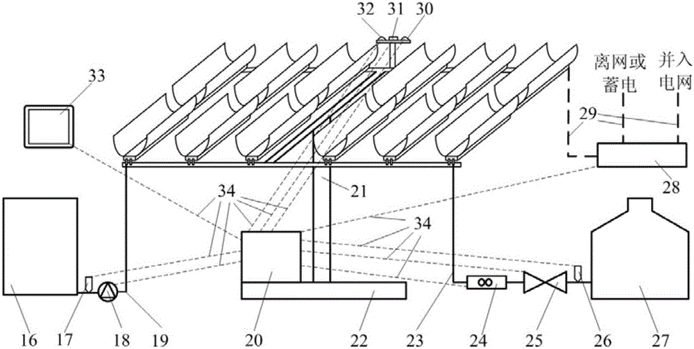
[0032]The present invention will be further described below in conjunction with the accompanying drawings. The nanofluid in the present invention is silicon dioxide nanofluid; the thermal insulation material in the present invention can be a material with thermal insulation function. The indoor monitoring module 33 is a computer.

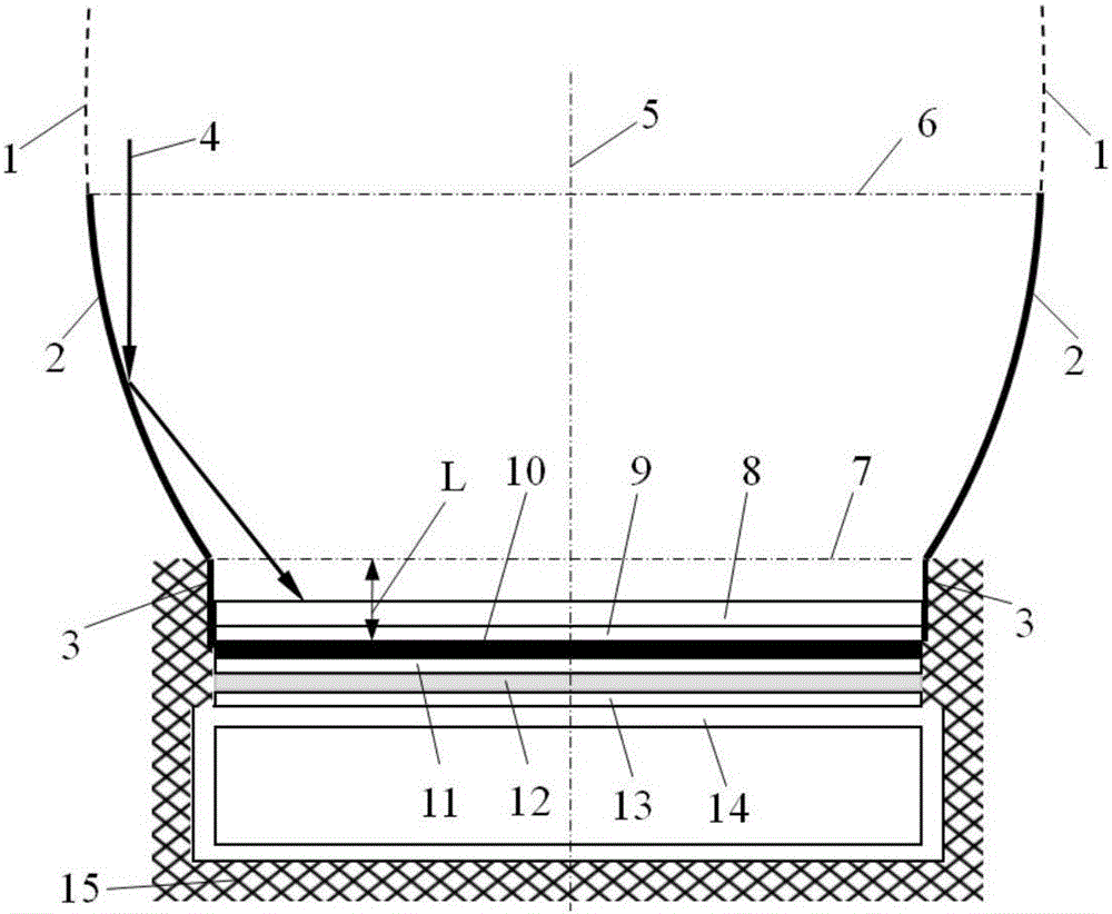
[0033] refer to figure 1 and figure 2 , a single-reflection compound parabolic concentrator concentrating heat and power cogeneration device of the present invention includes a concentrating photovoltaic photothermal unit array, a tracking unit, an electric recovery unit, a heat recovery unit, and a control and monitoring unit, wherein, figure 2 The concentrated photovoltaic photothermal unit array shown is composed of 12 figure 1 The single concentrated photothermal units shown are arranged.

[0034] The concentrated photovoltaic photothermal unit array includes several concentrated photovoltaic photothermal units, the concentrated photovolta...


PUM


Abstract

The invention relates to a cogeneration device for light condensation of a single-reflection compound parabolic condenser and an application method. The cogeneration device comprises a concentrating photovoltaic photothermal unit array, a tracking unit, an electricity recovery unit, a heat recovery unit and a control and monitor unit, direct sunlight parallel to the axis of the single-reflection compound parabolic condenser is reflected in one time by the single-reflection compound parabolic condenser, then sequentially passes through an ultra-white glass cover plate and an upper layer ethylene vinyl acetate (EVA) from top to bottom, and is converged to a crystalline silicon photovoltaic cell, the crystalline silicon photovoltaic cell generates electric energy and heat energy, the electric energy passes through a cable, is modulated by a photovoltaic inverter and then is incorporated into a power grid or used or stored in an off-grid way, and the heat energy is absorbed by a fluid passing through a cooling square pipe and then is introduced out for storage or application. The single-reflection compound parabolic condenser adopted by the invention is shorter than the traditional compound parabolic condenser and the traditional short and abrupt compound parabolic condenser, cost is low, high-quality electric energy can be generated, meanwhile, the heat energy can be provided, and high performance cost ratio is achieved.

Description

technical field [0001] The invention belongs to the research field of comprehensive utilization of concentrated photovoltaic light and heat, and relates to a concentrating heat and power cogeneration device utilizing a compound parabolic concentrator for concentrating light, in particular to a single reflection compound parabolic concentrator for concentrating heat and power cogeneration Device and method of use. Background technique [0002] For concentrators for comprehensive utilization of photovoltaic light and heat, trough, dish, spherical concentrating and Fresnel concentrating technologies are mainly used at present, and these concentrating technologies cannot use the scattered light of the sun; Concentrators, because their focusing planes are on the upper side of the mirror surface, the photovoltaic cell components or heat collectors installed at the focal plane will block part of the incident sunlight, thereby reducing the utilization rate of solar energy. In additi...

Claims


Application Information

Patent Timeline
Patent Type & Authority Applications(China)
IPC IPC(8): H02S10/30
CPCY02E10/50
Inventor 魏进家谢胡凌王泽昕高阳马秋鸣
Owner XI AN JIAOTONG UNIV
Why Eureka
Try Eureka