Eureka AIR delivers breakthrough ideas for toughest innovation challenges, trusted by R&D personnel around the world.

Bicycle pedal

A pedal and pedal shaft technology, applied in the field of pedals, can solve the problem of high manufacturing cost, and achieve the effects of high bearing capacity, high rigidity, gap-free, light-weight connection structure

Inactive Publication Date: 2007-03-07
INA SCHAEFFLER KG
View PDF12 Cites 2 Cited by
  • Summary
  • Abstract
  • Description
  • Claims
  • Application Information

AI Technical Summary

Problems solved by technology

[0004] The disadvantage of such a bicycle pedal is that it is expensive to manufacture due to the many parts and is therefore expensive

Method used


Image

  • Bicycle pedal
  • Bicycle pedal

Examples


Embodiment Construction

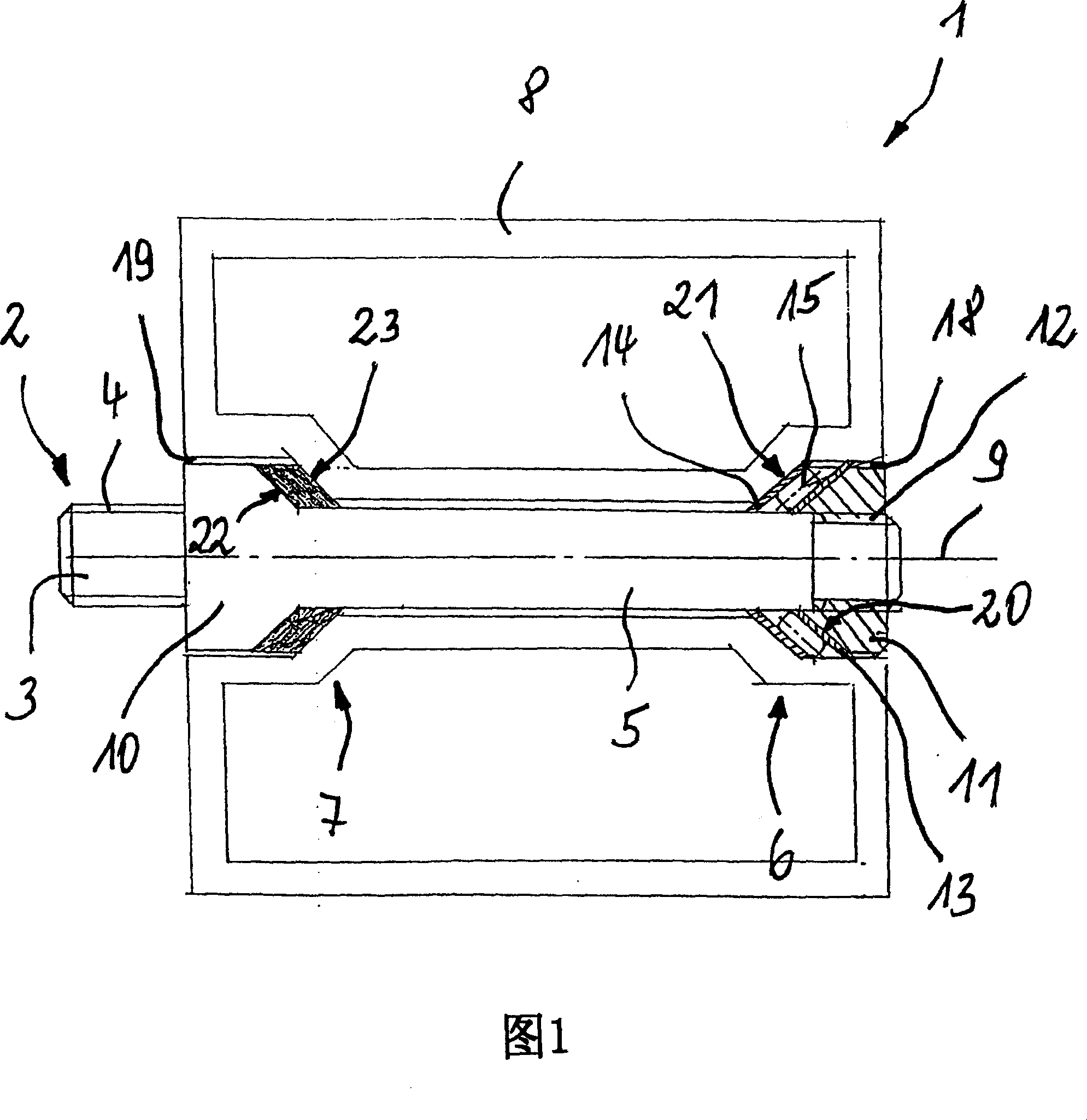
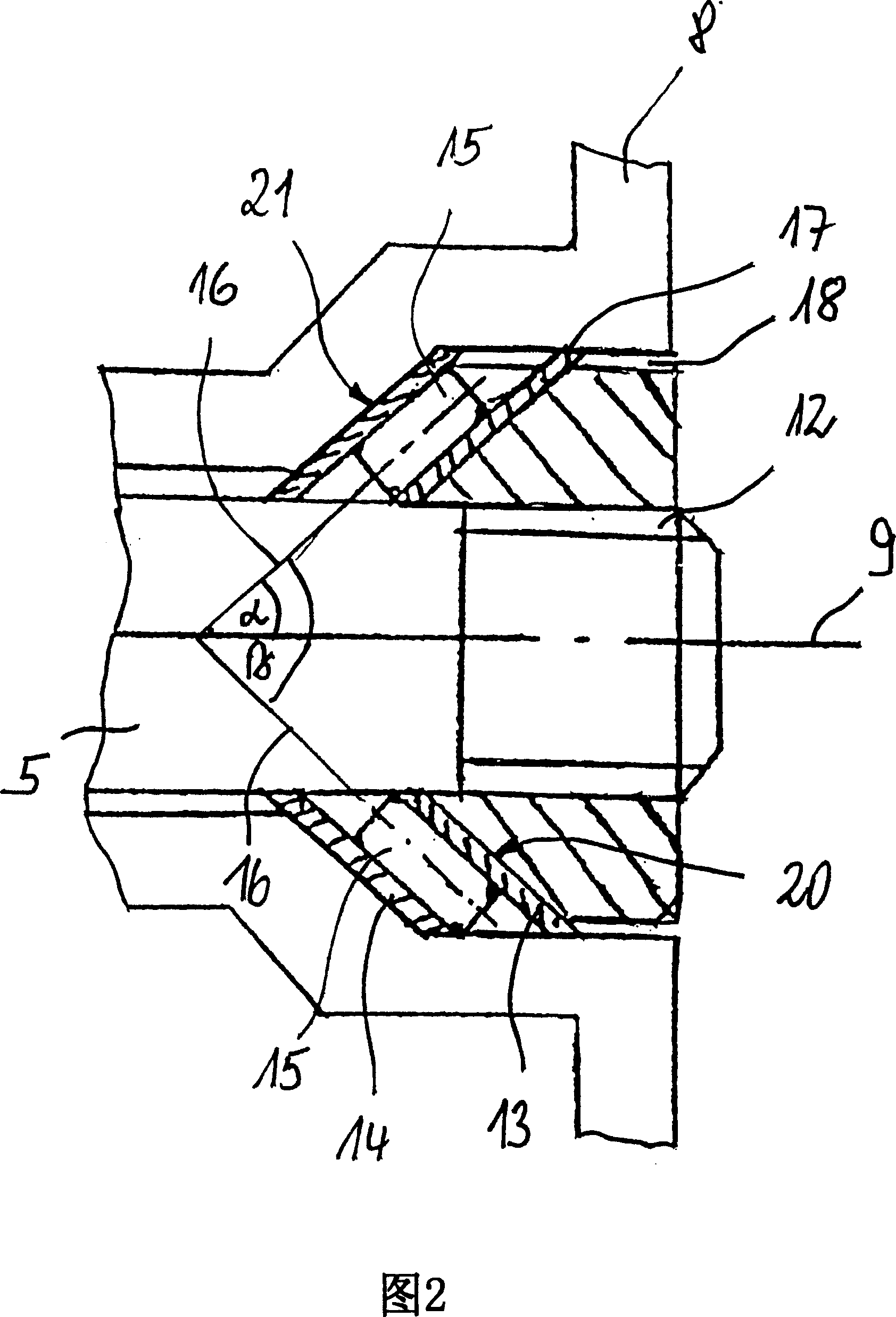
[0018] A bicycle pedal designed according to the invention and designated 1 is shown schematically in FIGS. 1 and 2 . The pedal consists of a pedal shaft 2 which has, at its left-hand end, a fastening pin 3 provided with an external thread 4 . This fastening journal is received by the inner edge hole of the crank arm, not shown in the figure. After the fastening journal 3 , the pedal shaft 2 transitions into a conical section 10 which has a conical bearing surface 22 inclined inwardly in the direction of the bearing axis 9 . Behind this conical bearing surface 22 the diameter of the pedal shaft 2 remains constant and ends at the right-hand end with the external thread 12 . The pedal shaft 2 is divided into a fastening journal 3 and a bearing journal 5 supporting a pedal body 8 . Furthermore, belonging to the bearing arrangement is a clamping screw 11 arranged on the right, which can be fastened to the external thread 12 of the bearing journal 5 via an internal thread (not sh...


PUM


Abstract

A bicycle pedal (1) rotates around a central main fixed shaft (2). Each end of the pedal is separated from the pedal shaft by a conical needle bearing. The cones are both directed inwards to the medal center.

Description

technical field [0001] The invention relates to a pedal, in particular a bicycle pedal, comprising a pedal shaft consisting of a fastening journal and a supporting journal, wherein the pedal shaft is connected to a crank arm via a threaded fastening journal and the supporting journal is passed through two Spaced apart rolling bearings receive the rotatable pedal body. Background technique [0002] A bicycle pedal of this type is known, for example, from DE 35 00 144 A1. In FIG. 3 of this publication is shown a pedal shaft which has a fastening journal at the left end which, through its external thread, can be screwed into the internal threaded inner edge of the crank arm. in the hole. After fastening the journal, the pedal shaft has a part that differs from the circle, through which it can be screwed into the inner edge hole of the crank arm by means of a suitable tool. The pedal shaft has an attached conical portion forming an inner raceway for the first ball bearing, th...

Claims


Application Information

Patent Timeline
Patent Type & Authority Applications(China)
IPC IPC(8): B62M3/08
CPCF16C19/36F16C33/58F16C33/588F16C19/54B62M3/08F16C19/361F16C19/46F16C19/548F16C2326/28
Inventor 马蒂亚斯·施佩伯
Owner INA SCHAEFFLER KG
Why Eureka
Eureka Blog
Learn More