Steam generator of washing machine
A technology of a steam generating device and a steam generator, which is applied in steam generating, washing devices, other washing machines, etc., and can solve the problems of the steam generator 200 such as deformation of the shell, damage of connecting parts, failure to ensure airtightness, etc.
Inactive Publication Date: 2007-03-07
NANJING LG PANDA APPLIANCES
0 Cites 1 Cited by
AI-Extracted Technical Summary
Problems solved by technology
[0023] As a result, the shells 211 and 212 of the steam generator 200 may be deformed, or the connecting parts of the water supply port 201 and the ...
Method used
1. Since a check valve is installed in the water supply port of the above-mentioned steam generator, the steam that flows back into the inside of the steam...
Abstract
This invention relates to washing machine steam generator, which comprises the following parts: generator used for water supply and steam exit; heating device to heat up water in generator; rotary drum to connected above steam exit to flow steam to supply tube, wherein, exit device to drain when the pressure in generator achieves certain value; anti-reverse device to prevent above generator steam flow to water supply.
Application Domain
Other washing machinesTextiles and paper +2
Technology Topic
EngineeringWater supply
Image
Examples
- Experimental program(1)
Example Embodiment
[0054] Here, the parts with the same structure in the prior art will be given the same names and the same reference numerals, and detailed descriptions thereof will be omitted.
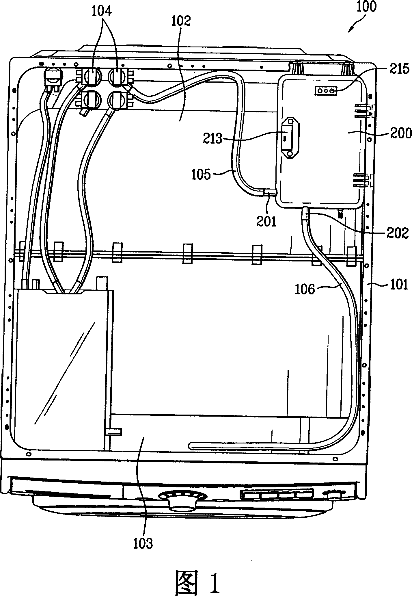
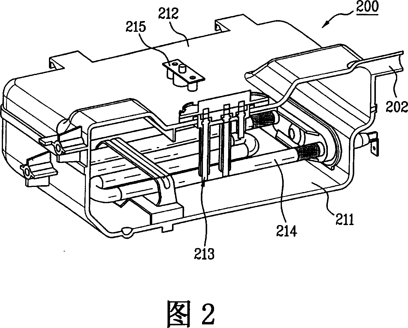
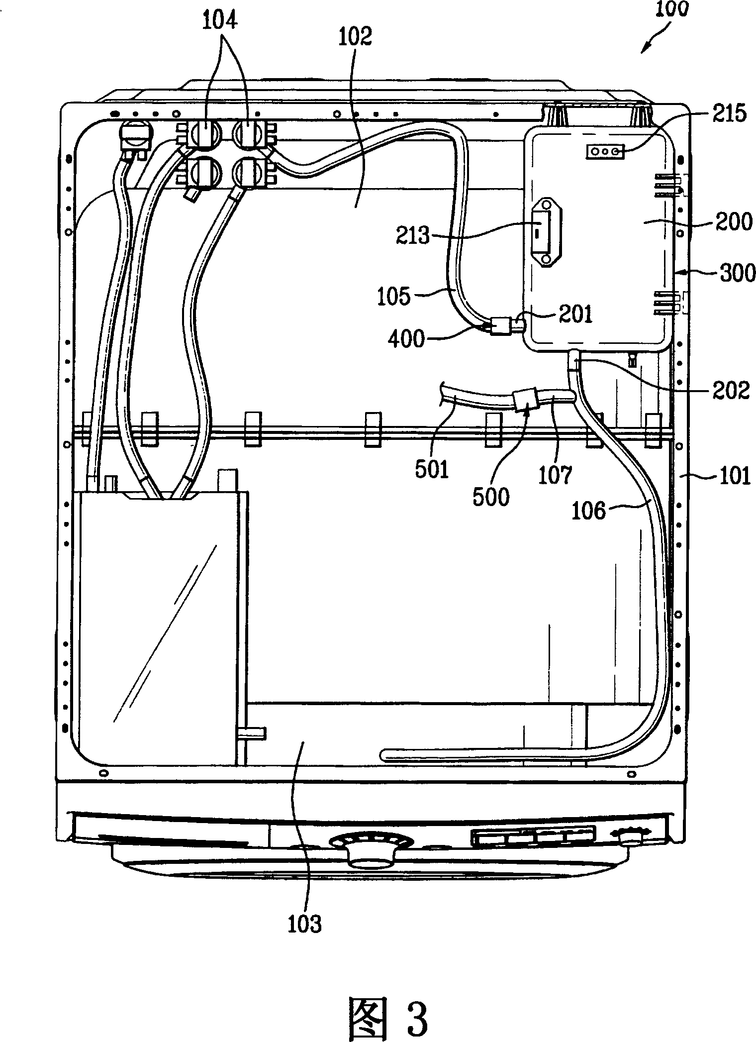
[0055] First, as shown in FIG. 3, the steam generating device 300 of the washing machine according to the embodiment of the present invention includes: a steam generator 200 for generating steam; a heater 214 for heating water supplied in the steam generator 200; The water supply port 201 installed on one side of the above-mentioned steam generator 200; the steam outlet 202 installed on the other side of the above-mentioned steam generator 200; the water supply pipe 105 connected to the above-mentioned water supply 201; Counter flow device 400; branch pipe 107 branched from the steam outlet 202; exhaust device 500 installed in the branch pipe 107.
[0056] Wherein, the water supply port 201 of the above-mentioned steam generator 200 is connected to the water supply pipe 105 connected to the water supply valve 104.
[0057] In addition, between the water supply pipe 105 and the water supply port 201, a check valve is installed as the backflow prevention device 400.
[0058] Here, the backflow prevention device 400 includes a body 401 having insertion holes formed in the front and rear directions, and a flow path member 403a that is installed inside the body 401 and used to guide the supplied water to the inside of the body 401 The opening and closing member 403b for opening and closing the flow path member 403a; the spring 404 for elastically supporting the opening and closing member 403b.
[0059] Wherein, the diameter of the inlet 402 of the flow path member 403a is smaller than the diameter of the opening and closing member 403b, and is formed obliquely toward the water supply pipe 105 connected to the main body 401, and the cross section of the flow path member 403a is generally a hollow trapezoid.
[0060] In addition, in order to selectively open and close the inflow port 402 inside the inclined surface of the flow path member 403a, the opening and closing member 403b is preferably made of a spherical shape.
[0061] In addition, the spring 404 is installed at a position between the opening and closing member 403b and the water supply port 201 of the steam generator 200, and is used to support the opening and closing member 403b.
[0062] Wherein, a boss 201a is formed at the entrance of the water supply port 201, and the spring 404 is provided on the boss 201a and supports the opening and closing member 403b.
[0063] In addition, in the steam generator 200, a steam discharge port 202 is formed on the other surface adjacent to the surface on which the water supply port 201 is formed, and the steam discharge port 202 is used to discharge the steam generated in the steam generator 200.
[0064] The steam outlet 202 is connected to the steam supply pipe 106. The end of the steam supply pipe 106 is connected to the drum 103 by a gasket (not shown) for sealing and connecting the front end of the washing tub 102 installed in the drum washing machine 100 and the housing 101.
[0065] Wherein, the steam supply pipe 106 is preferably installed in communication with the inside of the drum 103, and its end is preferably provided with a nozzle (not shown) in close proximity.
[0066] In addition, a branch pipe 107 is formed to branch from one side of the steam supply pipe 106 to the outside.
[0067] In addition, the end of the branch pipe 107 is connected to a safety valve 500 as an exhaust device.
[0068] In addition, the other side of the safety valve 500 that is not connected to the branch pipe 107 is connected to one end of the exhaust pipe 501. The exhaust pipe 501 is preferably connected to a drain flow path (not shown) connected to a drain pump (not shown). Show).
[0069] Hereinafter, the function and effect of the steam generating device in the embodiment of the present invention will be described in detail with reference to FIGS. 4a to 4c.
[0070] First, FIG. 4a illustrates a state where water is supplied from the water supply valve 104 installed in the above-mentioned drum washing machine 100 and supplied to the inside of the steam generator 200.
[0071] Among them, water with a predetermined pressure is supplied to the backflow prevention device 400 through the water supply pipe 105 connected to the water supply valve 104. Under the action of the pressure of the supplied water, the opening and closing member 403b in the backflow prevention device 400 will be Push to the water supply port 201 side of the steam generator 200 to open the opening and closing part 403 of the backflow prevention device 400 described above.
[0072] Thus, the water supplied from the water supply valve 104 will pass through the opening and closing portion 403 of the open backflow prevention device 400 and be supplied to the inside of the steam generator 200 through the water supply port 201 of the steam generator 200.
[0073] In addition, under the action of a water level sensor (not shown) installed in the steam generator 200, when an appropriate amount of water supply is completed, the water supply operation will be interrupted, thereby the opening and closing member 403b formed inside the backflow prevention device 400 , Under the action of the restoring force of the spring 404 supporting the opening and closing member 403b, it returns to the original position and closes the opening and closing portion 403.
[0074] In addition, the water supplied inside the steam generator 200 will be heated by a heater 214 installed at the inner bottom of the steam generator 200.
[0075] Hereinafter, referring to FIG. 4b, the flow path of the steam generated by the heated water will be described.
[0076] As described above, when the inside of the steam generator 200 reaches a certain level of water supply, the heater 214 will heat the supplied water and continue to generate steam.
[0077] The generated steam will pass through the steam outlet 202 and flow along the steam supply pipe 106. The flowing steam is discharged into the drum 103 through a nozzle formed at the end of the steam supply pipe 106.
[0078] Furthermore, when the steam flows along the steam supply pipe 106, it also flows into the branch pipe 107 branched from the outside of the steam supply pipe 106.
[0079] However, a safety valve 500 is installed on the other end of the branch pipe 107 branched from the steam supply pipe 106. Since the safety valve closes the discharge port 107a of the branch pipe 107, the steam cannot be discharged to the branch pipe 107. The outside of the discharge port 107a stays in the branch pipe 107.
[0080] In addition, when foreign substances accumulated in the nozzles block the nozzles, back pressure is generated in the steam supply pipe 106, or high-temperature steam is continuously discharged into the drum 103 of the drum washing machine 100, so that the inside of the drum 103 When the temperature rises, which causes the pressure inside the drum 103 to rise and a back pressure is generated, the safety valve 500 will be opened to reduce the back pressure generated.
[0081] Hereinafter, it will be described in detail with reference to FIG. 4c.
[0082] As described above, under the action of the back pressure generated above, the steam discharged to the drum 103 through the steam supply pipe 106 will flow back to the steam generator 200. And, when the steam inside the drum 103 passes through the steam supply pipe 106 and flows back to the inside of the steam generator 200, in addition to the inside of the steam generator 200, the steam inside the branch pipe 107 connected to the steam supply pipe 106 The pressure will rise immediately.
[0083] Here, when the pressure inside the steam generator 200, the steam supply pipe 106 and the branch pipe 107 rises above a certain pressure, the safety valve 500 will be turned into an open state, so that it cannot be discharged to the outside and stays there. The steam inside the steam generator 200 and the steam inside the branch pipe 107 are discharged to the exhaust pipe 501 through the open safety valve 500, so that the rising pressure in the steam generator 200 can be reduced.
[0084] At this time, the steam discharged through the exhaust pipe 501 is discharged to the outside through the aforementioned drain flow path connected to the drain pump.
[0085] Through the above operation, when the pressure in the steam generator 200 and the steam supply pipe 106 through which the steam flows is reduced, the possible damage to the connecting parts of the steam supply pipe 106 and the branch pipe 107 caused by high pressure can be prevented.
[0086] In addition, in the aforementioned embodiment of the present invention, the backflow prevention device 400 is installed in the water supply port 201. In another embodiment of the present invention to be described below, it is characterized in that the above-mentioned backflow prevention device 400 is installed in the water supply pipe 105.
[0087] Hereinafter, a detailed description will be given with reference to FIG. 5.
[0088] When performing a washing stroke of the drum washing machine 100, a motor (not shown) provided in the above drum washing machine 100 will rotate and perform the washing stroke operation. At this time, due to the rotational force of the motor, vibrations will be generated in the components including the body of the drum washing machine 100.
[0089] That is, since the flow path member 403a and the opening/closing member 403b constituting the backflow prevention device 400 are separately provided, under the influence of the above-mentioned vibration, a gap may occur, and thus an erroneous operation may occur.
[0090] In order to prevent the occurrence of the above-mentioned situation, the above-mentioned backflow prevention device 400 is installed in the above-mentioned water supply pipe 105. This prevents a gap between the flow path member 403a and the opening/closing member 403b under the influence of the vibration generated during the washing stroke.
[0091] In more detail, the water supply pipe 105 absorbs vibration at a time through components directly coupled with the drum washing machine 100, so that the generated vibration is rarely transmitted to the water supply pipe 105.
[0092] In addition, since the water supply pipe 105 is made of rubber material with excellent vibration absorbing ability, the vibration transmitted to the water supply pipe 105 will be smaller than other components incorporated in the drum washing machine 100.
[0093] As a result, the vibration transmitted in the backflow prevention device 400 installed in the water supply pipe 105 will be minimized, thereby preventing the occurrence of misoperation of the backflow prevention device 400, thereby causing the steam generation of the washing machine in another embodiment of the present invention. The device 300 has a good effect.
[0094] The above are only the preferred embodiments of the present invention, and are not intended to limit the present invention in any form. Any simple modification, equivalent change and modification made to the above embodiments based on the technical essence of the present invention still belong to Within the scope of the technical solution of the present invention.
[0095] The present invention has the following effects:
[0096] 1. Since a check valve is installed in the water supply port of the steam generator, it can prevent the steam that flows back into the steam generator from flowing back through the water supply port, thereby preventing the water supply that may occur due to contact with high-temperature steam Damage to pipes and water supply valves.
[0097]2. When the steam flowing back to the inside of the steam generator reaches a certain pressure, the steam will be discharged to the outside through the safety valve and reduce the internal pressure of the above-mentioned steam generator, which can prevent the high pressure inside the steam generator. The damage caused by the steam generator can also prevent damage to the connecting parts of the steam supply pipe and the water supply pipe connected to the steam generator.
PUM


Description & Claims & Application Information
We can also present the details of the Description, Claims and Application information to help users get a comprehensive understanding of the technical details of the patent, such as background art, summary of invention, brief description of drawings, description of embodiments, and other original content. On the other hand, users can also determine the specific scope of protection of the technology through the list of claims; as well as understand the changes in the life cycle of the technology with the presentation of the patent timeline. Login to view more.