
Fan and its flabellum

A fan and fan blade technology, applied in the field of fans and their fan blades, can solve the problems of inability to improve the air outlet efficiency of the fan 1, increase the energy consumption of the fan 1, reduce the working efficiency of the fan 1, etc., so as to delay the stall and improve the air outlet efficiency. Increase and improve the effect of quality

Active Publication Date: 2007-03-07
DELTA ELECTRONICS INC
View PDF0 Cites 1 Cited by
  • Summary
  • Abstract
  • Description
  • Claims
  • Application Information

AI Technical Summary

Problems solved by technology

In this way, even if the speed of the fan 1 is increased again, the air volume cannot be increased, which is the so-called "stall" phenomenon (stall)
[0005] At this time, not only the air outlet efficiency of the fan 1 cannot be improved, but even noise will be generated, which not only increases the energy consumption of the fan 1, but also reduces the working efficiency of the fan 1

Method used


Image

  • Fan and its flabellum
  • Fan and its flabellum
  • Fan and its flabellum

Examples


Embodiment Construction

[0022] A fan and its blades according to several embodiments of the present invention will be described below with reference to the relevant drawings.

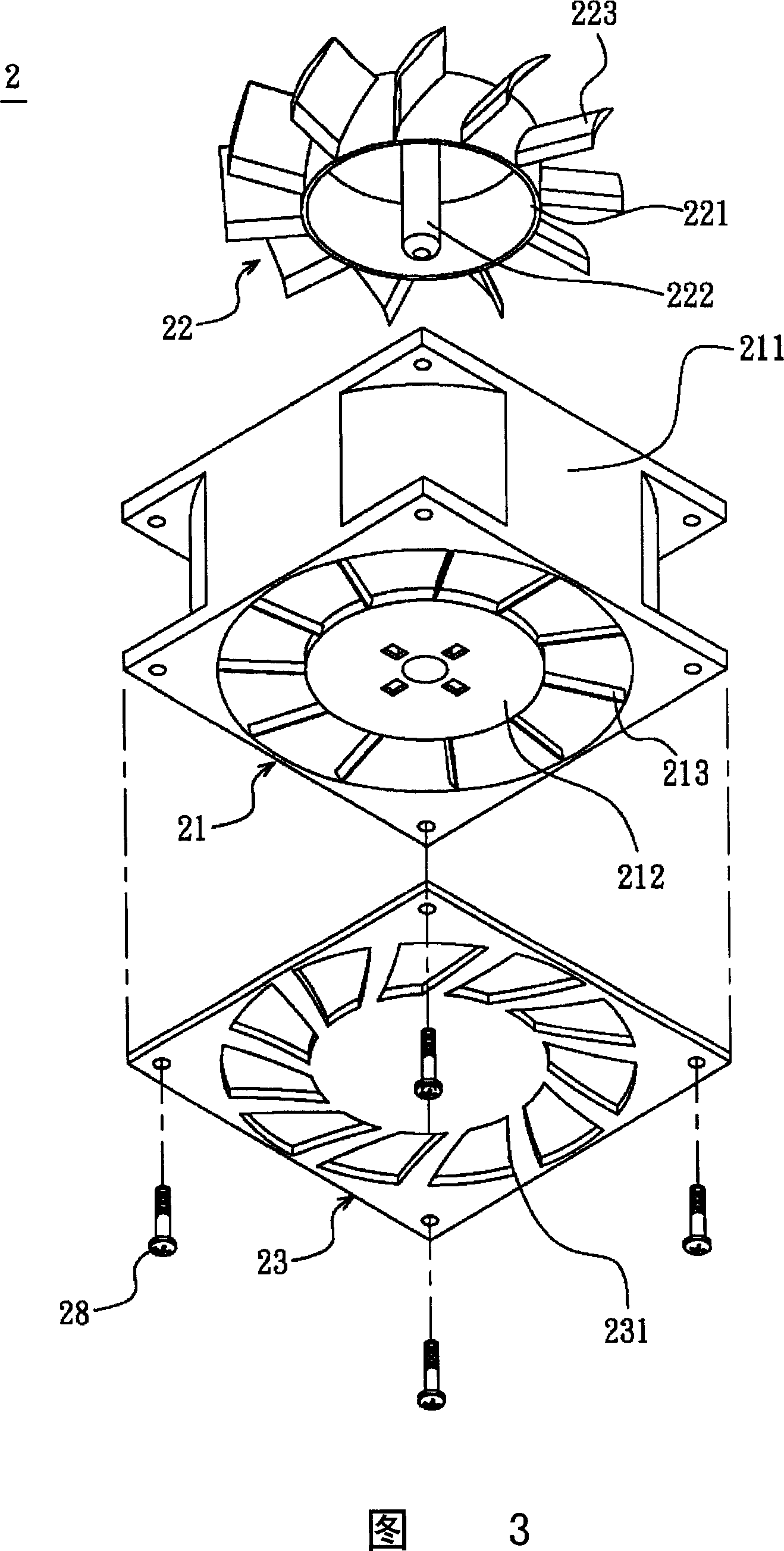
[0023] Please refer to FIG. 3 , which is the fan 2 according to the first embodiment of the present invention, including a frame 21 and an impeller 22 .

[0024] The fan frame 21 has a shell 211 with a base 212 inside, and a plurality of vanes 213 or ribs are connected between the shell 211 and the base 212 . In addition, a motor (not shown in the figure) may also be provided on the base 212 .

[0025] The impeller 22 has a hub 221 and a plurality of fan blades 223 surrounding the hub 221 . A rotating shaft 222 protrudes from the center of the hub 221 . The rotating shaft 222 is axially disposed in the base 212 of the fan frame 21 , and the impeller 22 is driven to rotate by the motor.

[0026] Next, please refer to FIG. 4 , each fan blade 223 has a main wing 223a and a flap 223b respectively, and each fan blade 223 has a wi...


PUM


Abstract

This invention relates to fan, which comprises one fan frame and one blade, wherein, turbine axis is set into frame with several fan blades with one main fin and one assistant fin with one preset angle. This invention also discloses one fan blade.

Description

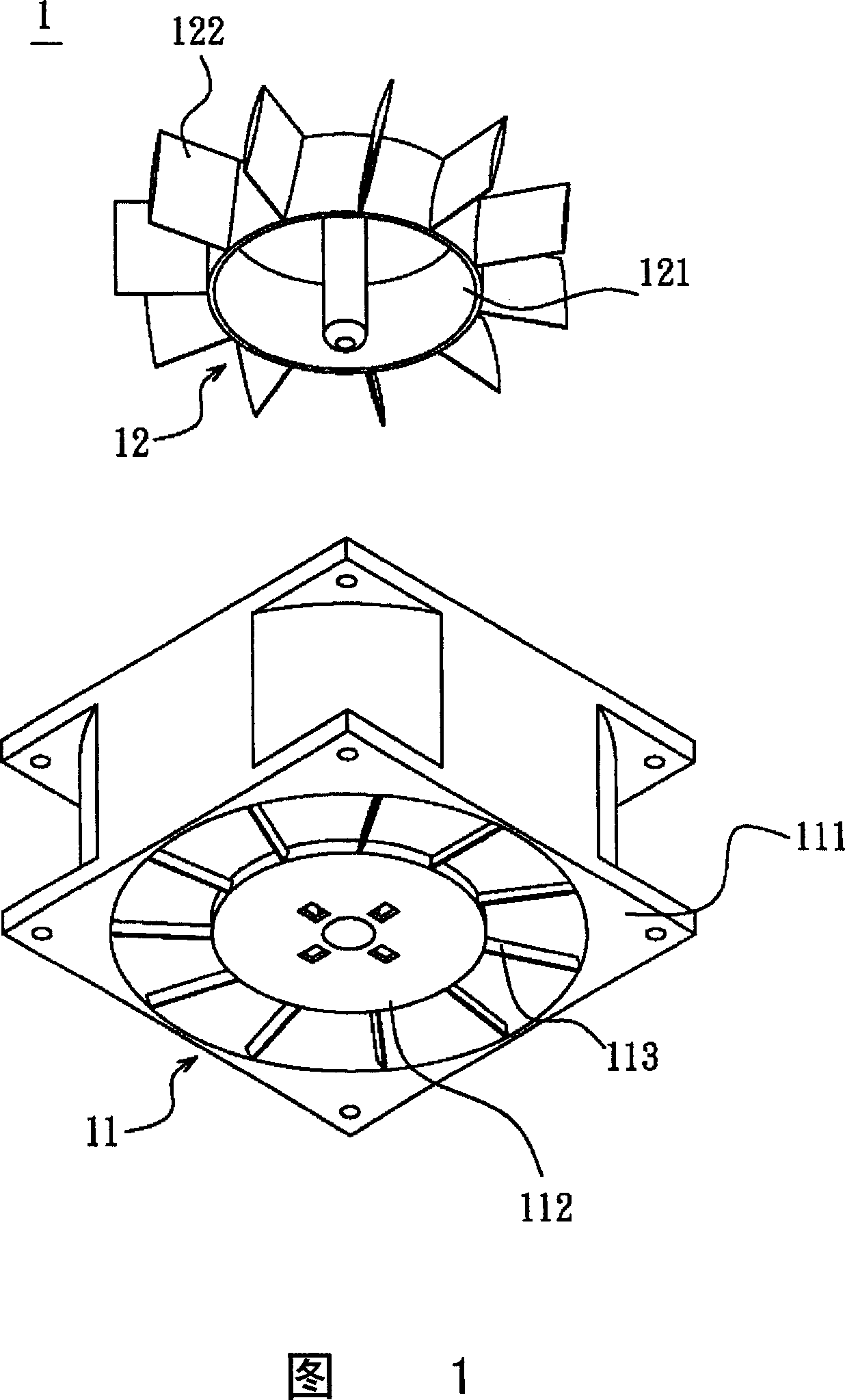
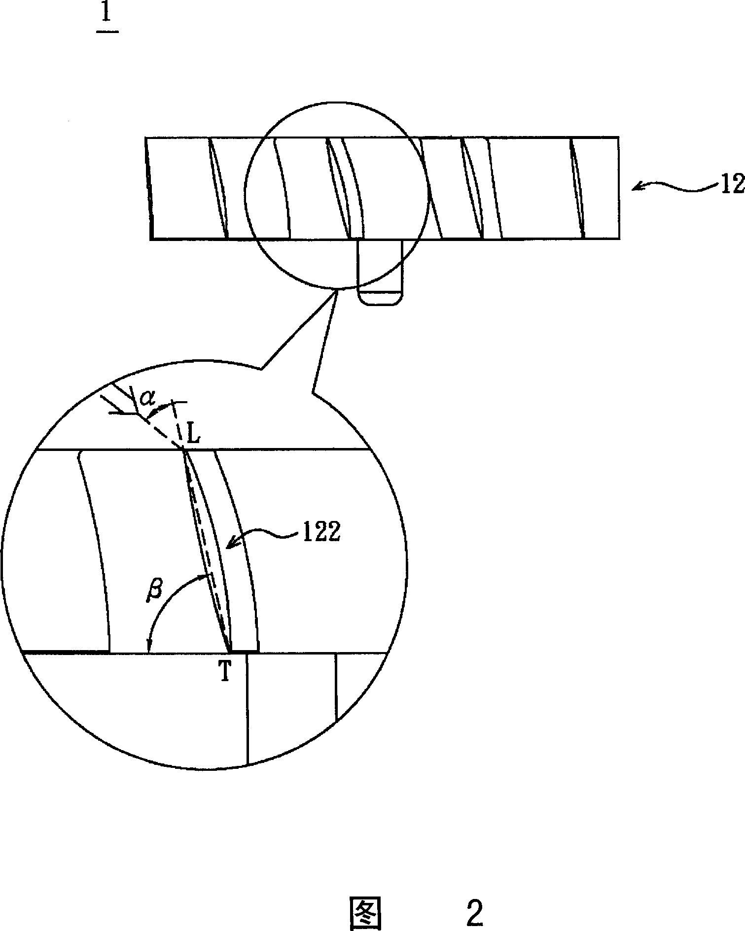
technical field [0001] The invention relates to a fan, in particular to a fan with better air outlet effect and its fan blades. Background technique [0002] Please refer to FIG. 1 , which is a conventional fan 1 which generally includes a frame 11 and an impeller 12 . The fan frame 11 has a housing 111 and a base 112 , and a plurality of ribs 113 are connected between the housing 111 and the base 112 . In addition, a motor (not shown) is disposed on the base 112 . The impeller 12 has a hub 121 and a plurality of fan blades 122 arranged around the hub 121. The impeller 12 is arranged on the base 112 of the fan frame 11 by means of the hub 121, and is driven by a motor to rotate relative to the base 112. Then, each fan blade 122 respectively compresses the air nearby, so that the fan 1 achieves the effect of blowing out wind. [0003] Please refer to FIG. 2 , which is an enlarged view of a single airfoil fan blade 122 in the existing impeller 12, wherein, the connection lin...

Claims


Application Information

Patent Timeline
IPC IPC(8): F04D29/38F04D25/08
Inventor 李嵩蔚张楯成黄文喜
Owner DELTA ELECTRONICS INC
Learn More