
Method for improving air conditioner refrigeration efficiency and control device thereof

A control device and technology for air conditioners, applied in heating and ventilation control systems, heating methods, space heating and ventilation, etc., and can solve problems such as the decrease in the utilization rate of the condenser, the increase in the compression ratio, and the increase

Inactive Publication Date: 2007-03-07
樊远征
View PDF0 Cites 2 Cited by
  • Summary
  • Abstract
  • Description
  • Claims
  • Application Information

AI Technical Summary

Problems solved by technology

As a result of the increase in condensing temperature, the cooling capacity decreases, the compression ratio increases, and the compressor motor current increases, which ultimately reduces the cooling energy efficiency ratio.
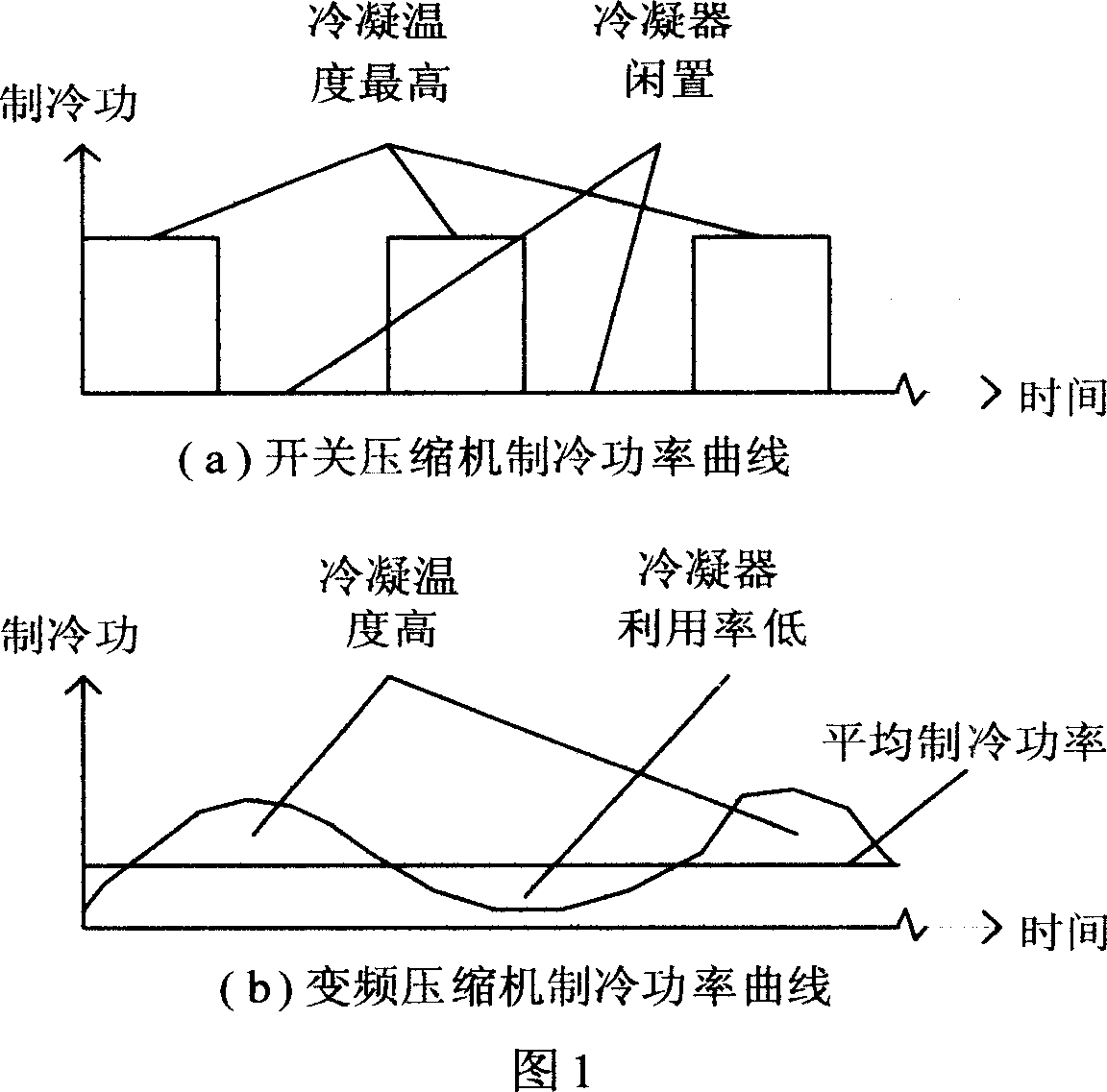
[0004] Figure 1(b) describes the cooling power curve of the inverter compressor. When the cooling power of the compressor is lower than the average cooling power, the utilization rate of the condenser decreases; when the cooling power of the compressor is higher than the average cooling power, the condensation heat is obtained. If it is not removed in time, the condensation temperature will rise, and eventually the refrigeration energy efficiency ratio will be reduced.

Method used


Image

  • Method for improving air conditioner refrigeration efficiency and control device thereof
  • Method for improving air conditioner refrigeration efficiency and control device thereof
  • Method for improving air conditioner refrigeration efficiency and control device thereof

Examples


Embodiment 1

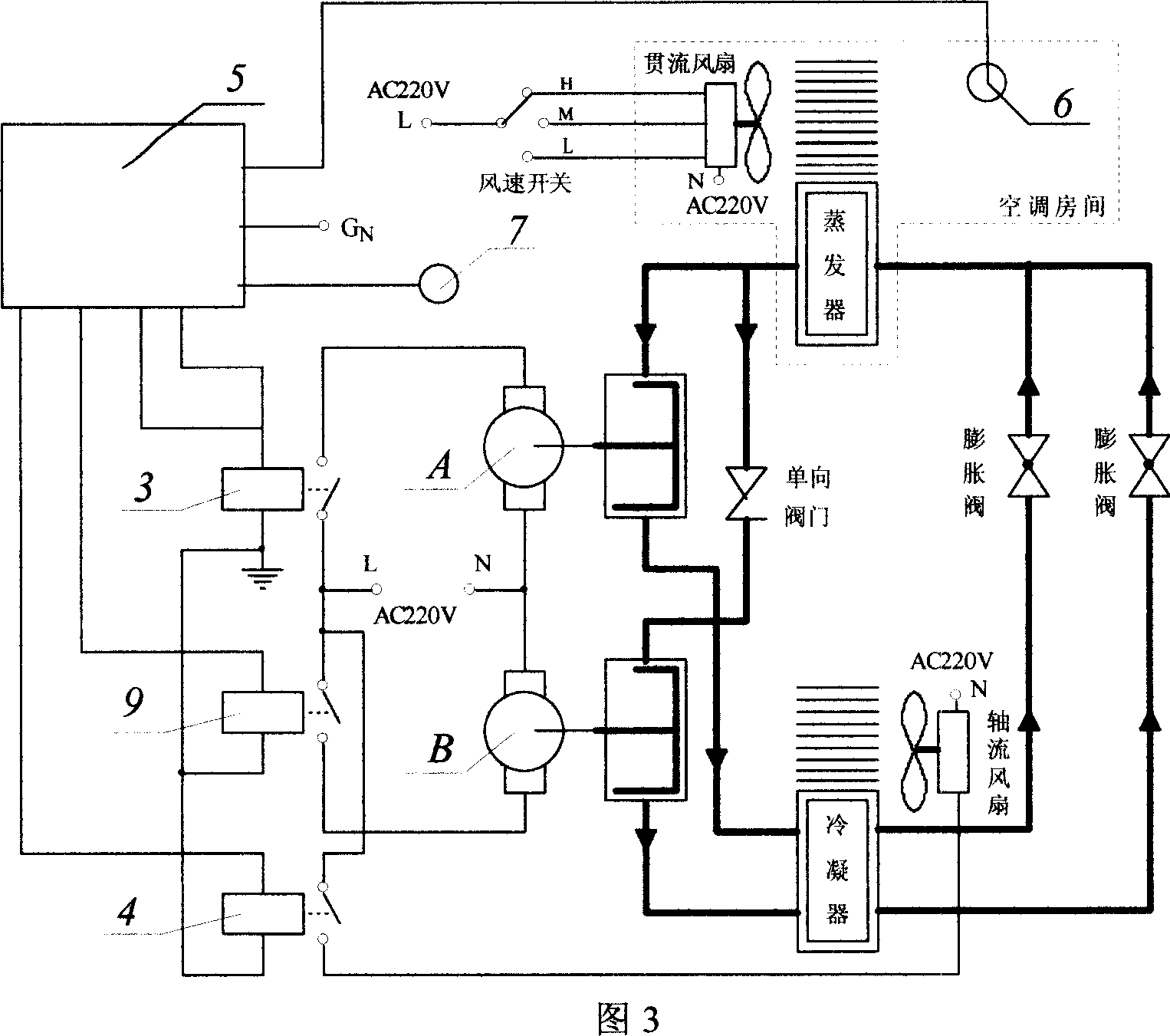
[0021] Here take the common household air conditioner in the current market as an example, the refrigerating compressor in this air conditioner is used as the said B machine of the present invention, and then select the constant speed compressor A machine whose power is only 1 / 5 of the B machine, in this Under the control of the control device described in the invention, a novel air conditioner of "continuous system, intermittent adjustment" is formed, and referring to Fig. 3 below, its operating conditions are as follows:

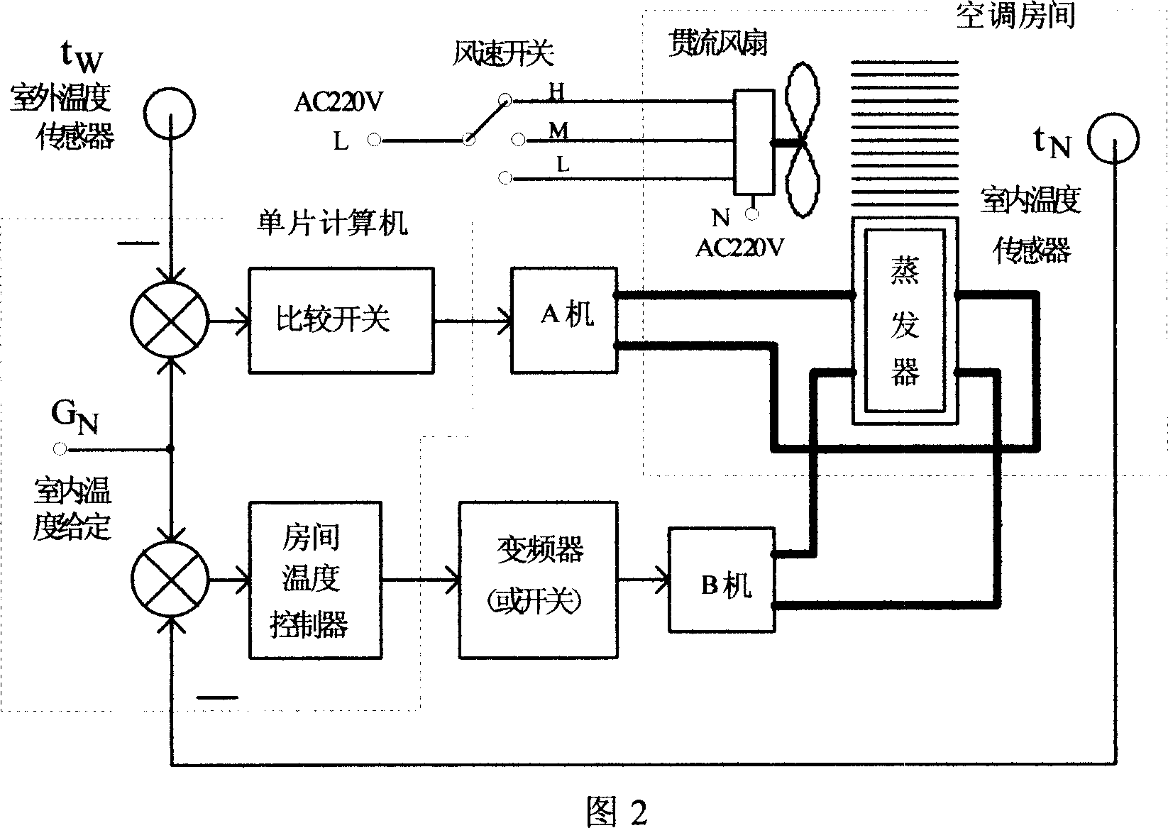
[0022] After the air conditioner was powered on, the single-chip computer (5) was initialized first according to the main program of Fig. 5, and then, the given temperature G was processed. N such as G N =25°C, and deal with the indoor temperature t converted by AD N and outside temperature t W data; then, compare the outdoor temperature t W and a given temperature G N To determine the working status of machine A, when t W N When machine A stops, when...

Embodiment 2

[0024] Here take the current market variable frequency household air conditioner as an example, the refrigerating compressor in this air conditioner is used as the said B machine in the past of the present invention, and then select the fixed speed compressor A machine whose power is only 1 / 5 of the B machine, in this air conditioner Under the control of the present invention, also constitute a novel air conditioner of "continuous system, intermittent adjustment", see Fig. 4 below, its operation situation is as follows:

[0025] After the air conditioner was powered on, the single-chip computer (5) was initialized first according to the main program of Fig. 5, and then, the given temperature G was processed. N such as G N =25°C, and deal with the indoor temperature t converted by AD N and outside temperature t W data; then, compare the outdoor temperature t W and a given temperature G N To determine the working status of machine A, when t W N When machine A stops, when t ...


PUM


Abstract

This invention provides one cooling control mode to improve cooling effect, which adopts cooling system with A and B compressors and cooling device for continuous cooling through invention, wherein, the B machine is controlled by cooling control mode to improve condensator dissipation utility more than 30 percentage and to lower condensator temperature more than 4 degrees to realize cooling effect comparing with air conditioning effect improved by 30 to 40 percentage and to reduce start times by 50 percentage to save relative start consumption.

Description

technical field [0001] The invention relates to a method for improving the cooling energy efficiency of an air conditioner and its control device, in particular to a method for improving the cooling energy efficiency by changing the cooling control mode and its corresponding controller. technical background [0002] Traditional air conditioners use switching compressors or variable frequency compressors to adjust the cooling capacity to match the cooling load, so that the heat dissipation of the condenser is sometimes high and sometimes low, or fluctuates from time to time, thereby reducing the utilization rate of the condenser and increasing the condensation rate. Average temperature, resulting in low cooling efficiency. for example: [0003] The cooling power curve of the on-off compressor described in Fig. 1(a) shows that the condenser is idle when the compressor is shut down, which reduces the utilization rate of the condenser; while when the compressor is turned on, th...

Claims


Application Information

Patent Timeline
IPC IPC(8): F24F11/00
Inventor 樊远征
Owner 樊远征
Learn More