Catheter for diagnostic imaging and therapeutic procedures

A catheter assembly, vessel technology, applied in the direction of catheters, hypodermic injection devices, etc.

Inactive Publication Date: 2007-03-07
MEDRAD INC.
View PDF6 Cites 8 Cited by
  • Summary
  • Abstract
  • Description
  • Claims
  • Application Information

AI Technical Summary

Problems solved by technology

Another disadvantage of this catheter design is that its large side holes prevent fine dispersion of fluid from the distal end compared to the invention disclosed below

Method used


Image

  • Catheter for diagnostic imaging and therapeutic procedures
  • Catheter for diagnostic imaging and therapeutic procedures
  • Catheter for diagnostic imaging and therapeutic procedures

Examples


Embodiment Construction

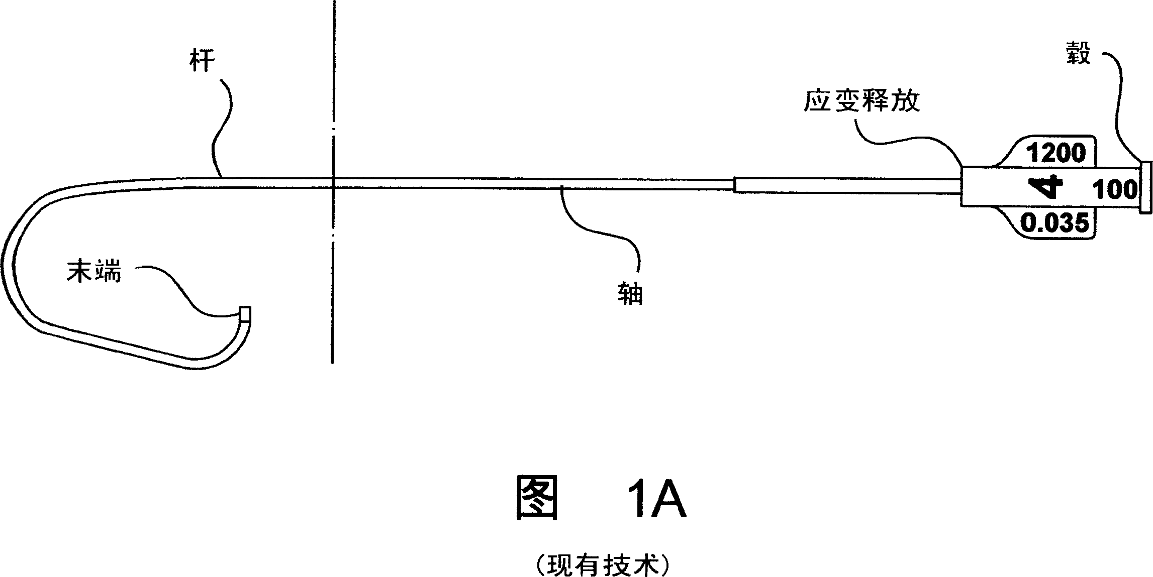
[0069] 4A-4H illustrate several embodiments and various preferred and alternative aspects of the present invention, namely, a catheter that can be used for diagnostic imaging, therapeutic therapy, and various other diagnostic and interventional procedures. As with many prior art catheters noted in the background, the catheter assembly of the present invention will also generally include a hub, a strain relief, a shaft, and a shaft. Although the invention has been described and illustrated herein primarily for cardiac or angiographic catheters, the reader should understand that the invention is applicable or adapted to catheters of various types, shapes, sizes and uses.

[0070] 4A-4R illustrate a first embodiment of the invention along with various preferred and alternative aspects. Catheter 100 includes a shaft equipped with a porous portion 200 and a restrictor 300 attached to the distal end of the shaft. As shown in Fig. 4B, for a catheter 100 made in 4 French gauge, the l...


PUM


Abstract

A catheter for use in introducing fluid into a vessel or other bodily structure. The catheter comprises a stem and a restrictor. The stem has approximate a distal end thereof a porous section that defines microholes distributed thereabout, which are inclined by a predetermined angle in the proximal direction. Affixed to the stem, the restrictor includes a conic ally-shaped valve with an apex thereof defining an opening and pointing in the proximal direction. The opening generally decreases in size as the conically-shaped valve flattens out distally as the pressure of the fluid within the tip increases. The forces of the fluid flowing out of the opening of the restrictor and out of the microholes of the stem substantially balance thereby substantially eliminating both recoil and whipping of the catheter, thus enabling its position to remain exceptionally stable while the fluid is finely dispersed therefrom in a cloud-like form.

Description

[0001] related application [0002] This application claims priority to US Provisional Application No. 60 / 520,071, filed November 15, 2003, which is incorporated herein by reference. technical field [0003] The present invention generally relates to catheters in use for diagnostic imaging, therapeutic therapy, drug delivery, perfusion, and various other interventional procedures requiring the supply of fluid into a patient's vasculature or other structures. In particular, the present invention relates to a catheter having an innovative distal end that maintains a particularly stable position within the vasculature or other structure, while at the same time permits very fine dispersion of fluid therefrom during such procedures. Background technique [0004] The following material is provided to assist the reader in understanding the invention disclosed hereinafter and at least some of the many applications in which the invention is typically used. This information is also p...

Claims


Application Information

Patent Timeline
Patent Type & Authority Applications(China)
IPC IPC(8): A61M5/00A61M25/00A61M
CPCA61M25/01A61M2025/0057A61M25/007A61M25/0041A61M25/0068A61M25/0043A61M2025/0076A61M25/0069A61M2025/0073A61M25/008A61M25/0074
Inventor G·G·布鲁克S·D·萨维奇J·R·加德纳F·W·特朗布利
Owner MEDRAD INC.
Why Eureka
Try Eureka