Composite cold stamping mold

A technology of cold stamping and mold, which is applied in the field of composite mold structure of various cold stamping processes

Inactive Publication Date: 2007-03-14
丝艾产品标识(天津)有限公司
View PDF0 Cites 32 Cited by
  • Summary
  • Abstract
  • Description
  • Claims
  • Application Information

AI Technical Summary

Problems solved by technology

But these three schemes are far from meeting the requirements of modern production with high precision, low cost and high benefit

Method used


Image

  • Composite cold stamping mold

Examples


Embodiment Construction

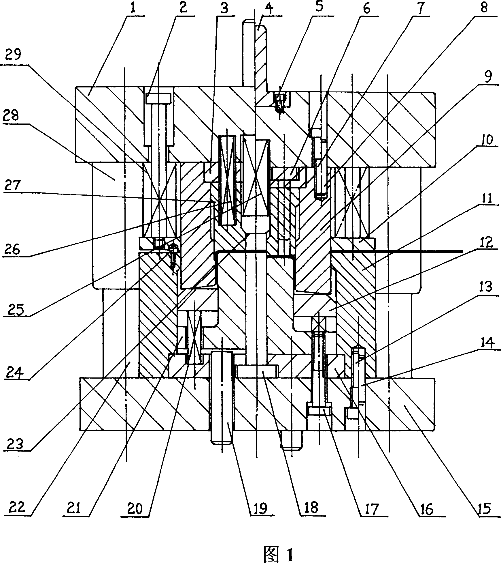
[0013] As shown in Figure 1, the composite cold stamping die of the present invention includes two parts, an upper die and a lower die. The upper mold is composed of the upper mold base 1, the mold handle 4 directly installed on the upper center of the upper mold base 1 through the positioning hole and the screw 5, and respectively installed under the upper mold base 1 through the positioning hole, the backing plate 25, the screw 7 and the pin 8 Guide sleeve 28, guide post 6, punch and die 9, spring 25, spring 26, ejector 27 and ejector block 23 installed in punch and die 9, are installed on the upper die through unloading screw 2 and unloading spring 29 The unloading plate 10 around the convex and concave die 9 under the seat 1 is composed of; The lower mold is composed of the lower mold base 15, the guide post 22 directly installed on the lower mold base 15 through the positioning hole, the die 11 installed in the center of the lower mold base 15 through the screw 13 and the...


PUM


Abstract

The invention relates to a compound cold punching mould. Wherein, it comprises upper and lower moulds; the upper mould is formed by upper mould base 1, discharge screw 2, pad plate 3, mould handle 4, first screw 5, first guide post 6, second screw 7, pin 8, convex-concave mould 9, discharge plate 10, lift block 23, first spring 25, second spring 26, lifter 27, guide muffle 28, and third spring 29; the lower mould is formed by concave mould 11, top plate 12, third screw 13, positioning pin 14, lower mould base 15, fixing plate 16, limit screw 17, convex mould 18, support rod 19, lift spring 20, bend convex mould, second guide post 22, and baffle pin 24; the convex-concave mould 9 and the first guide post 6 are mounted under the upper mould base 1; the lift block 22 and the lifter 27 are mounted inside the convex-concave mould 9; the guide muffle 28 is mounted under the upper mould base 1; the second guide post 13 is mounted on the lower mould base 15; the concave mould 11 is mounted on the lower mould base; the convex mould 18 and the bend convex mould 21 are mounted inside the concave mould 11; and the lower mould via second guide post 22 and guide muffle 28 is matched with the upper mould.

Description

technical field [0001] The invention relates to a compound cold stamping die, in particular to a composite die structure of multiple cold stamping processes. Background technique [0002] At present, there are three basic process schemes for forming U-shaped bending parts with holes on the bottom surface: [0003] (1) Single process forming of blanking, bending and punching; [0004] (2) Blanking, punching and compounding, and then bending and forming in a single process; [0005] (3) Forming in a single process of blanking, followed by bending and punching composite forming. [0006] Scheme (1) has a simple mold structure and requires 3 sets of molds, and the efficiency and precision are relatively low; schemes (2) and (3) have a slightly more complicated structure, requiring 2 sets of molds, and both efficiency and precision are improved. But these three schemes are far from meeting the requirements of modern production with high precision, low cost and high benefit. ...

Claims


Application Information

Patent Timeline
IPC IPC(8): B21D37/10B21D37/12
Inventor 聂福荣靳伍银阎峰云冯辉霞马栋林王毅
Owner 丝艾产品标识(天津)有限公司
Why Eureka
Try Eureka