
Apparatus for dynamically debugging a multi-node network

A technology for dynamic debugging and node equipment, which is applied in data exchange network, software testing/debugging, instrumentation, etc., and can solve problems such as packet loss of interest, data buffer overflowing quickly, etc.

Active Publication Date: 2007-03-14
INT BUSINESS MASCH CORP
View PDF2 Cites 2 Cited by
  • Summary
  • Abstract
  • Description
  • Claims
  • Application Information

AI Technical Summary

Problems solved by technology

The drawback of this solution is that the data buffer will overflow very quickly and packets of interest will be lost
Also, this solution does not trigger data collection based on the occurrence of a problem
Another drawback is that any group analysis requires post-processing of the data

Method used


Image

  • Apparatus for dynamically debugging a multi-node network
  • Apparatus for dynamically debugging a multi-node network
  • Apparatus for dynamically debugging a multi-node network

Examples


Embodiment Construction

[0015] The object of the present invention is a system and method for collecting information related to anomalies at the first error detection and dynamically collecting said information at execution time.

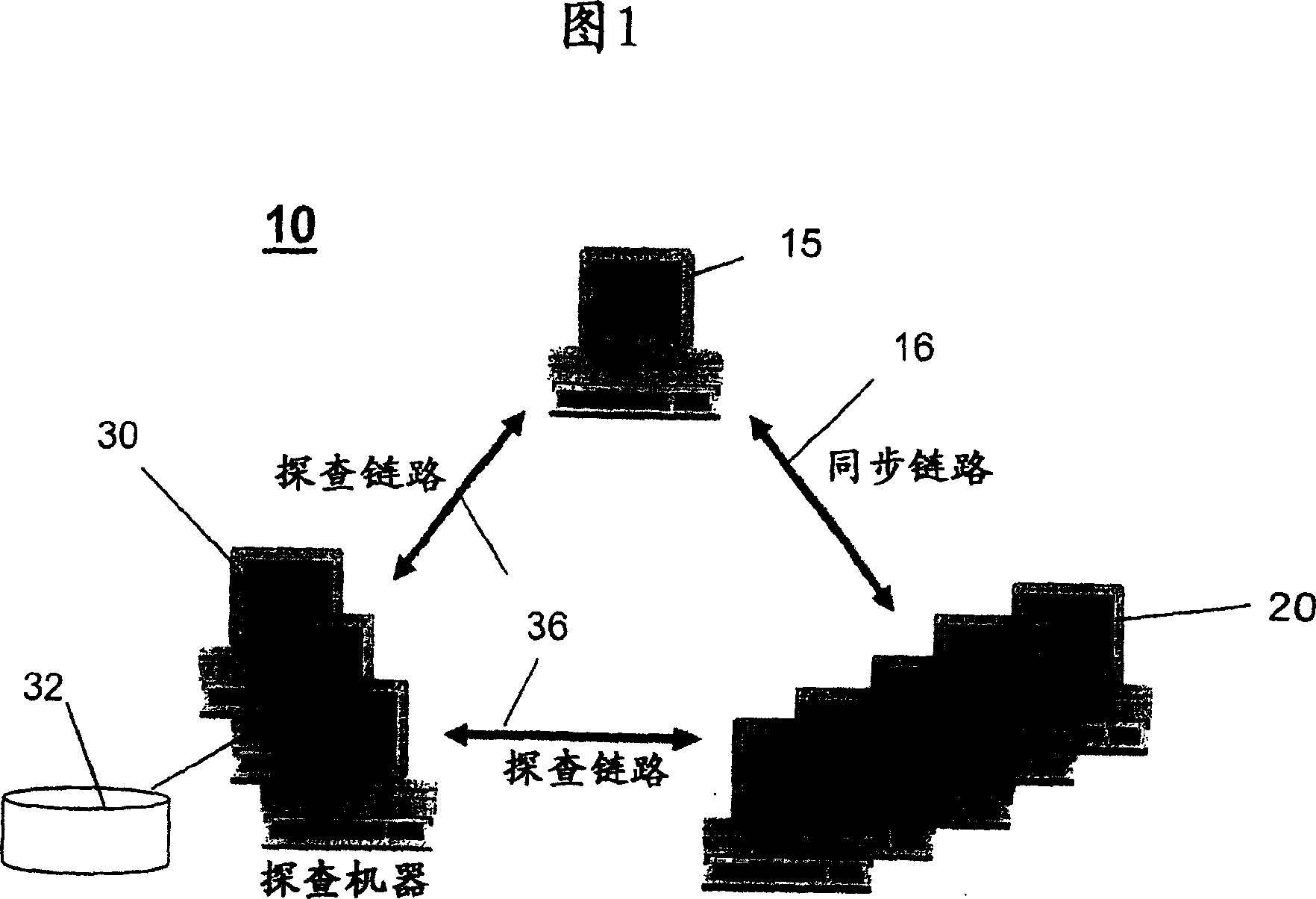
[0016] FIG. 1 illustrates a networked system 10 implementing a system and method of collecting information related to program failures occurring at nodes of networked computers, wherein debugging information is collected upon first error detection and dynamically collected at execution time. information. In one embodiment, the system 10 includes one or more server devices 15 or client devices 20, where each device 15, 20 is referred to interchangeably as a Central Electronics Complex (CEC), which generally means a packaged A processor complex of a single entity. For example, a CEC 15, 20 may contain an IBM System z9, or an IBM eServer  zSeries  (eg zSeries 990 (z990) or zSeries 890 (z890)) system. In Figure 1, a first CEC or server node 15 is shown connected to one ...


PUM


Abstract

A system, method and computer program product for dynamically debugging a multi-node network comprising an infrastructure including a plurality of devices, each device adapted for communicating messages between nodes which may include information for synchronizing a timing clock provided in each node. The apparatus comprises a plurality of probe links interconnecting each node with a probe device that monitors data included in each message communicated by a node. Each probe device processes data from each message to determine existence of a trigger condition at a node and, in response to detecting a trigger condition, generates a specialized message for receipt by all nodes in the network. Each node responds to the specialized message by halting operation at the node and recording data useful for debugging purposes. In this manner, debug information is collected at each node at the time of a first error detection and collected dynamically at execution time without manual intervention.

Description

technical field [0001] The present invention relates to a multi-processor / multi-node network, and more particularly to a system and method for dynamically monitoring network packets transmitted between nodes, detecting errors and collecting debugging data at nodes in real time. Background technique [0002] Currently, in a multi-processor / multi-node networked system, a problem may occur with one processor, but due to the slow response of monitoring tools / personnel monitoring the system, and the number of nodes involved in the network, support for this problem Debugging data may be lost. The problem is further complicated if, in order to debug the problem, data with simultaneous time stamps from many nodes / systems in many locations is required. [0003] US Patent No. 5119377 describes a problem management system for networked computer systems whereby error detection codes are placed within software programs during software development. When an error or failure is detected a...

Claims


Application Information

Patent Timeline
Patent Type & Authority Applications(China)
IPC IPC(8): H04L12/26G06F11/36
CPCG06F11/3632G06F11/3636
Inventor 威廉·M·萨卡尔丹尼斯·M·塞维格尼斯科特·M·卡尔森多纳德·克拉特里特雷沃·E·卡尔森乔纳桑·D·布拉巴利戴维·A·埃尔克米切尔·亨利·索多尔·哈克老罗纳德·M·斯密斯张立
Owner INT BUSINESS MASCH CORP
Learn More