Vehicular display device
A display device and display design technology, which is applied to vehicle components, measurement value indication, and the value of multiple variables at the same time, and can solve the problem of lack of aesthetic decorative appearance of vehicle display devices
- Summary
- Abstract
- Description
- Claims
- Application Information
AI Technical Summary
Problems solved by technology
Method used
Image
Examples
no. 1 example
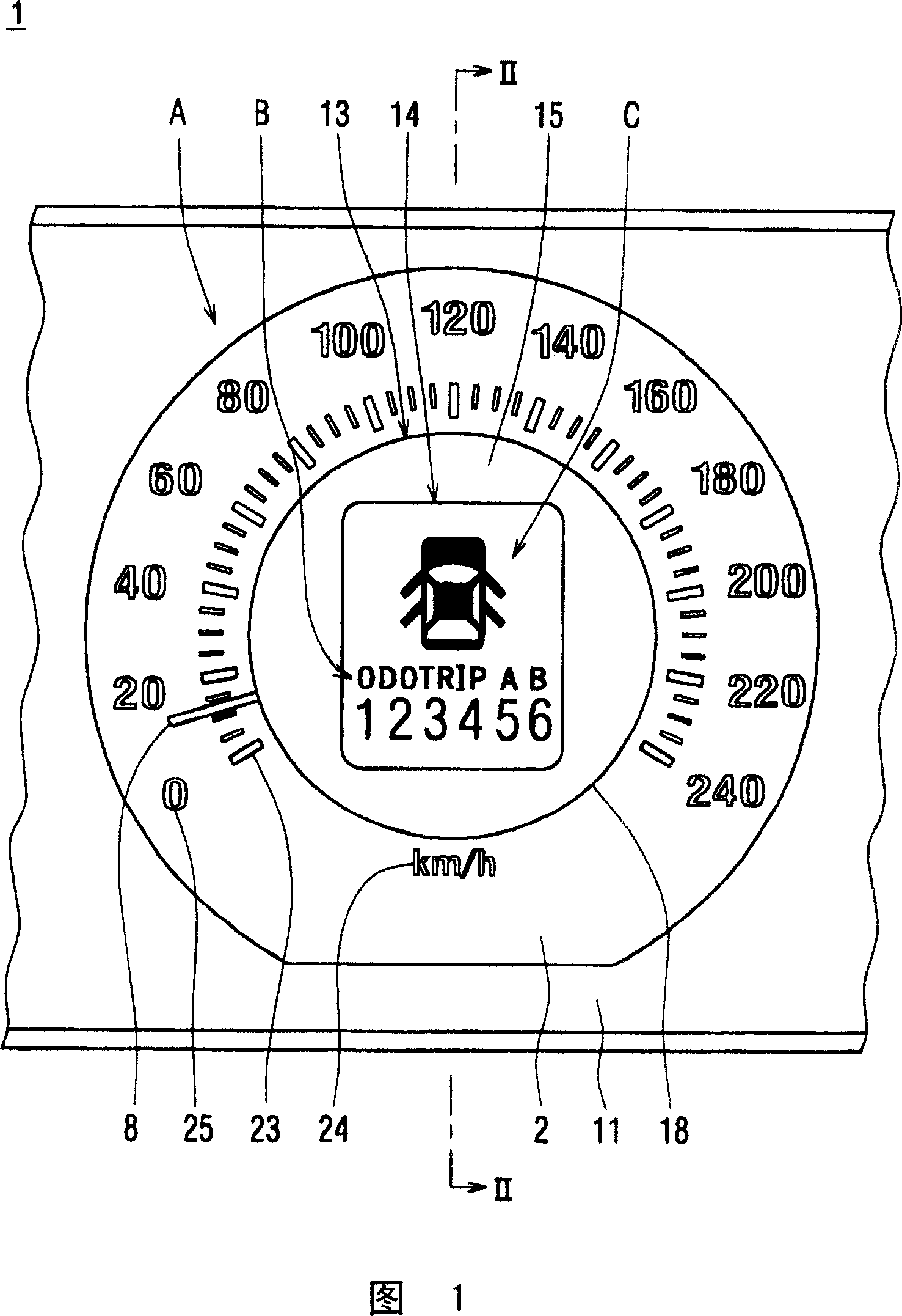
[0032] FIG. 1 is a partial front view of a combination meter 1 according to a first embodiment of the present invention.
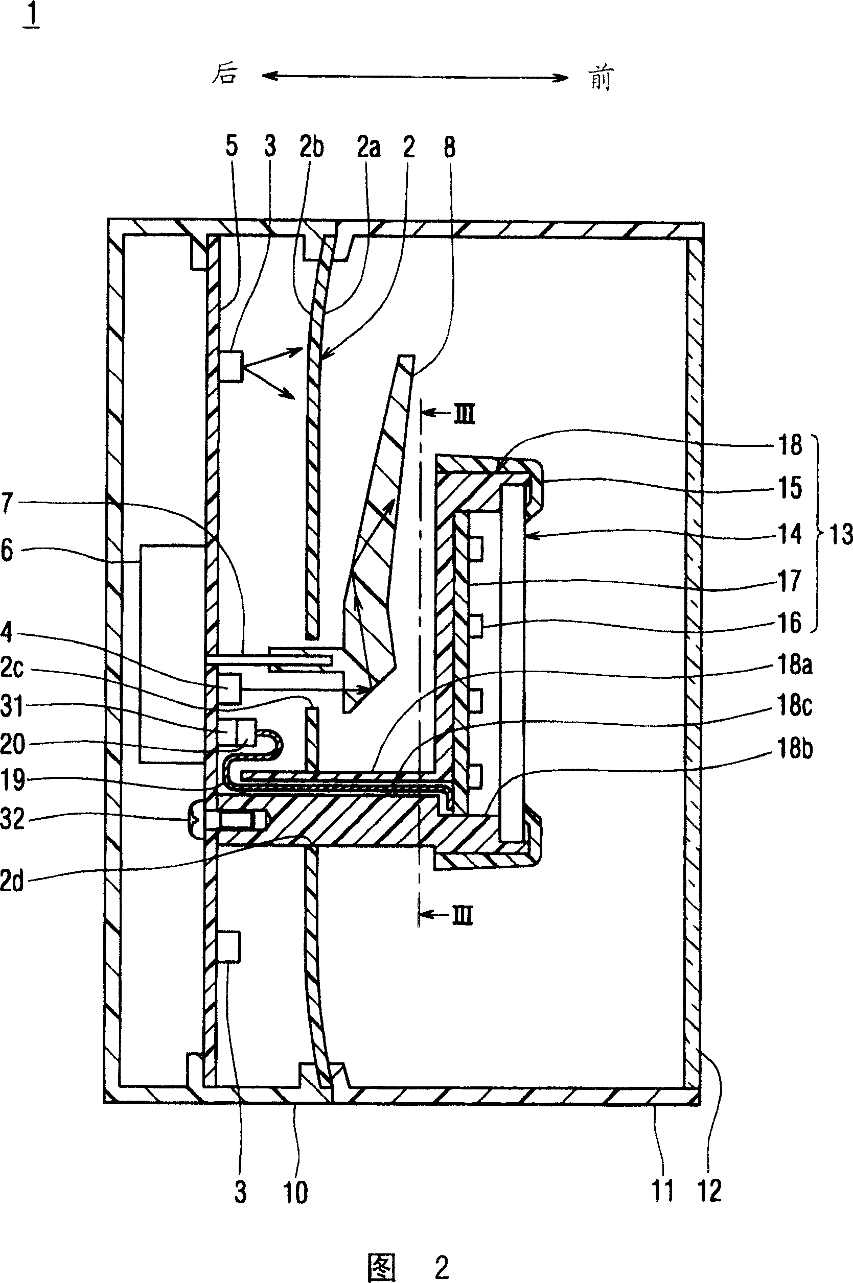
[0033] Fig. 2 is a sectional view taken along line II-II in Fig. 1 . In FIG. 2 , the right side surface faces the driver's seat from which the combination meter 1 is visible.
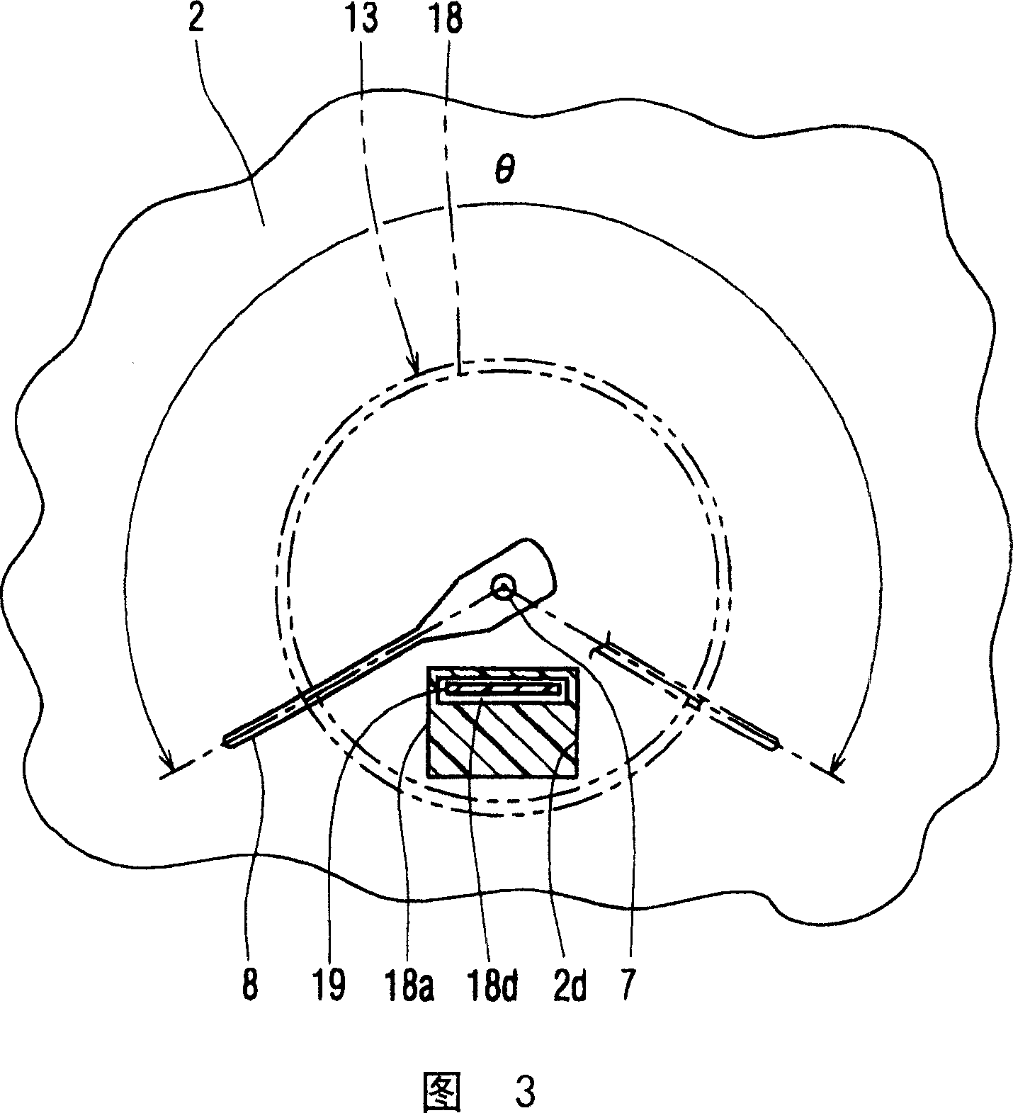
[0034] FIG. 3 is a view illustrating the inner surface of the combination meter 1 . In FIG. 3 , scales 23 , characters 24 and numbers 25 are omitted for ease of understanding.
[0035] FIG. 4 is a diagram illustrating a circuit configuration of the combination meter 1 .
[0036] The combination meter 1 is installed in the vehicle so that the driver in the driver's seat can observe the combination meter 1 . The instrument cluster 1 displays various information related to the vehicle. The combination meter 1 includes a speedometer A indicating the traveling speed of the vehicle, a rangefinder B indicating the cumulative traveling distance and section traveling distance, and a door...
no. 2 example
[0071] 5 is a sectional view of the combination meter 1 according to the second embodiment and corresponds to a sectional view taken along line II-II in FIG. 1 .
[0072] The combination meter 1 according to the second embodiment differs from the first embodiment in the fixing of the center panel 13 to the speedometer A. As shown in FIG.
[0073] As shown in FIG. 5 , the supporting plate 40 is provided as a supporting unit to support and fix the central panel 13 . The support plate 40 is formed of a transparent material such as transparent polycarbonate. The support plate 40 is closer (to the right in FIG. 5 ) to the observer than the speedometer A or the pointer 8 in the viewing direction (horizontal direction in FIG. 5 ). In detail, the reflector 18 is fitted in the engagement hole 40 a provided in the support plate 40 .
[0074] The reflector 18 has a guide portion 18d instead of the attachment portion 18a of the first embodiment, as shown in FIG. 5 . The guide portion 1...
no. 3 example
[0078] 6 is a sectional view of the combination meter 1 according to the third embodiment and corresponds to a sectional view taken along line II-II in FIG. 1 .
[0079] The combination meter 1 according to the third embodiment differs from the second embodiment in the structure of the support plate 40 . The characters 24 and numbers 25 of the display design in the speedometer A are formed on the support plate 40 .
[0080] As shown in FIG. 1, characters 41 and numerals 42 are formed on the rear surface 41 of the support plate 40 by forming an opaque colored layer or a translucent colored layer using printing or hot stamping.
[0081] In addition, light emitting diodes 43 are mounted on the printed circuit board 17 of the center panel 13 as light sources for illuminating characters 41 and numerals 42, as shown in FIG. 6 .
[0082] Combination meter 1 according to the third embodiment can provide the same effects as those of the first embodiment. The central panel 13 appears ...
PUM
 Abstract
Description
Claims
Application Information
 - R&D
- Intellectual Property
- Life Sciences
- Materials
- Tech Scout
- Unparalleled Data Quality
- Higher Quality Content
- 60% Fewer Hallucinations
Browse by: Latest US Patents, China's latest patents, Technical Efficacy Thesaurus, Application Domain, Technology Topic, Popular Technical Reports.
© 2025 PatSnap. All rights reserved.Legal|Privacy policy|Modern Slavery Act Transparency Statement|Sitemap|About US| Contact US: help@patsnap.com


