Eureka AIR delivers breakthrough ideas for toughest innovation challenges, trusted by R&D personnel around the world.

Combustor for stove

A technology for burners and stoves, which is applied in the direction of burners, gas fuel burners, and combustion methods. It can solve the problems of easy adhesion of soup to the flame hole, cumbersome maintenance of burners, etc., and achieve good maintainability.

Inactive Publication Date: 2007-03-21
RINNAI CORP
View PDF0 Cites 2 Cited by
  • Summary
  • Abstract
  • Description
  • Claims
  • Application Information

AI Technical Summary

Problems solved by technology

[0003] Although the burner with a flame hole on the top cover of this burner has good thermal efficiency, the boiled soup is easy to adhere to the flame hole.
Furthermore, the boiled soup falls into the burner main body through the flame hole and the communication hole, and the maintenance of the burner becomes cumbersome.

Method used


Image

  • Combustor for stove
  • Combustor for stove
  • Combustor for stove

Examples


Embodiment Construction

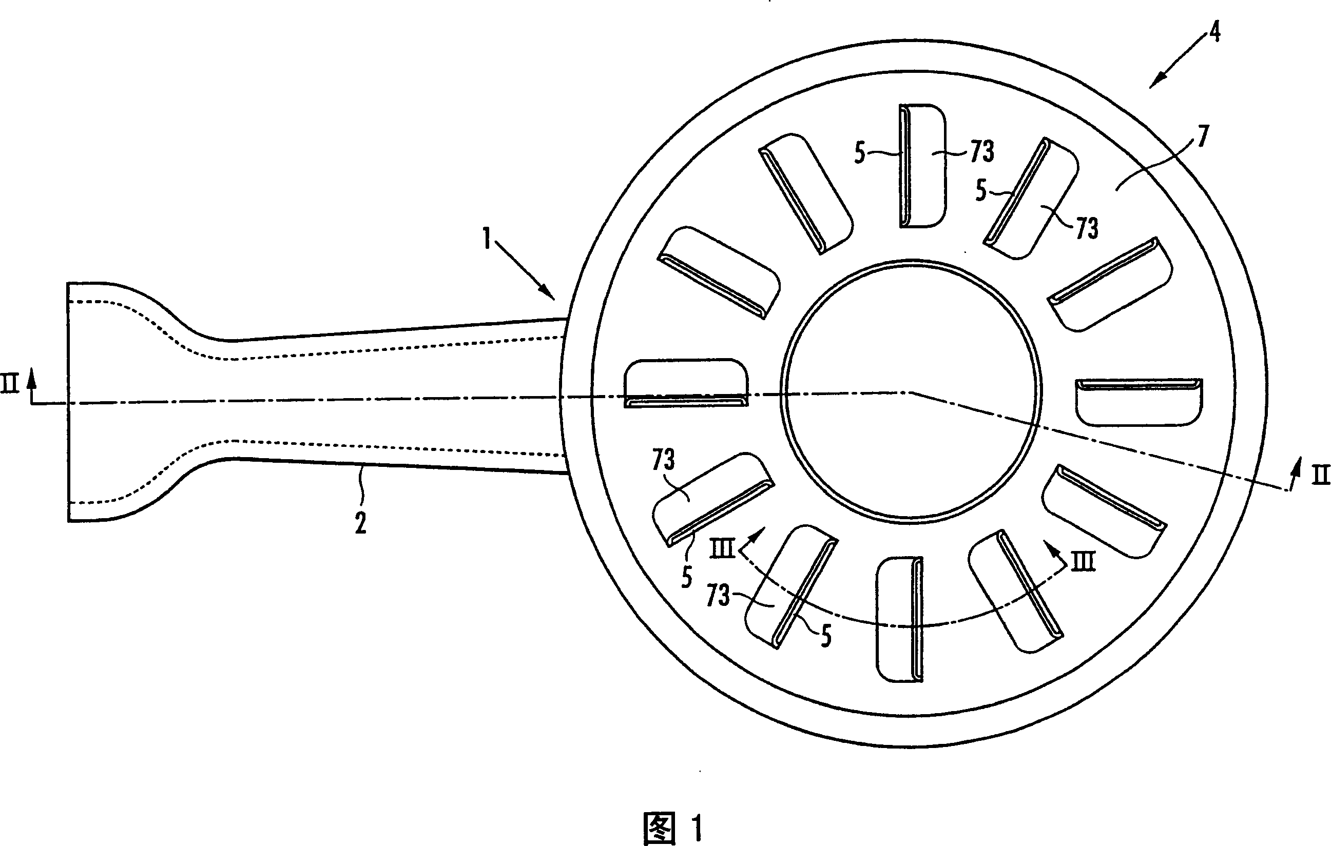
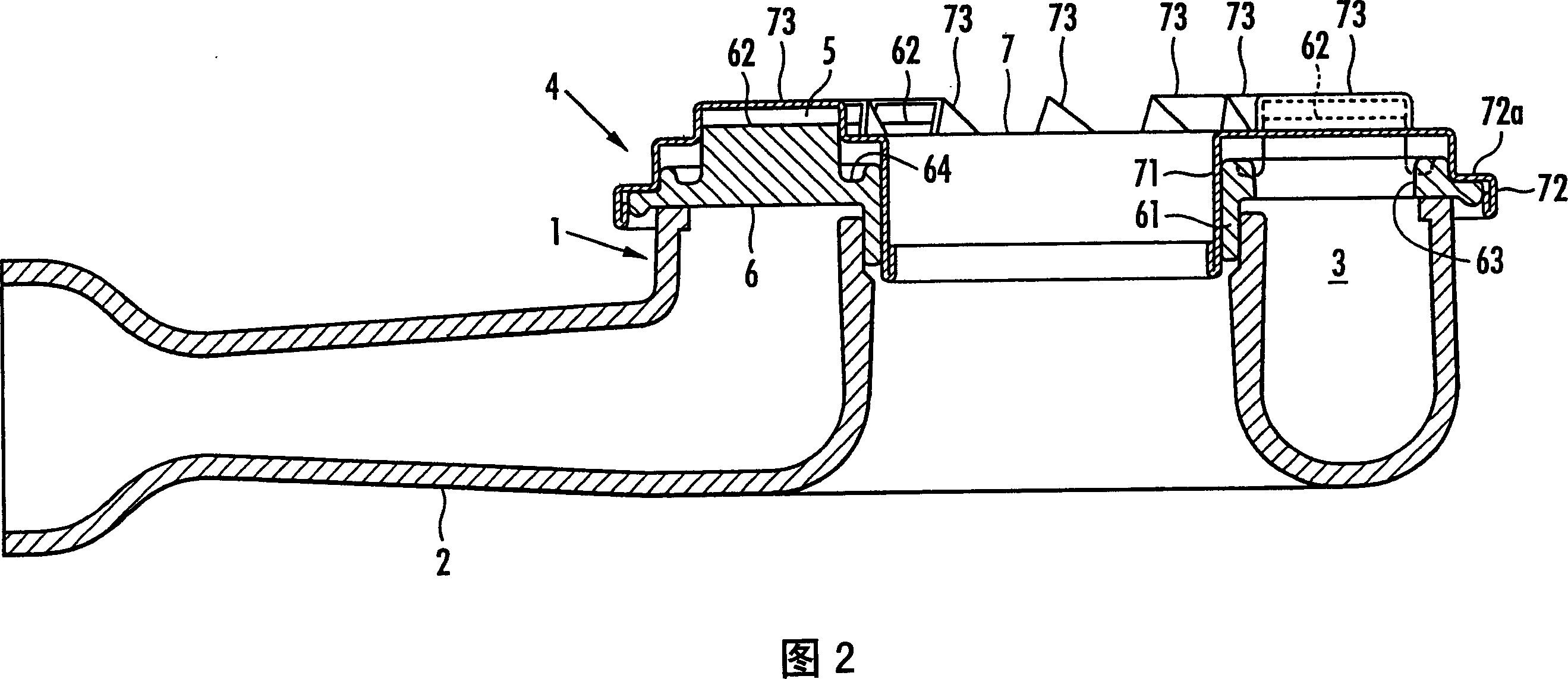
[0014] Referring to Fig. 1 and Fig. 2, 1 is a burner body of a burner for a stove. A mixing tube 2 is integrally formed on the burner body 1 . At the portion of the burner body 1 at the front end of the mixing tube 2, an annular gas distribution chamber 3 with an upward opening is formed. Furthermore, a burner roof 4 covering the gas distribution chamber 3 from above is provided. On the upper surface of the burner top cover 4, a plurality of radial flame holes 5 are arranged at intervals in the circumferential direction. The gas is caused to be ejected from each flame hole 5 with a motion component directed in one direction (counterclockwise in FIG. 1 ) in the circumferential direction.

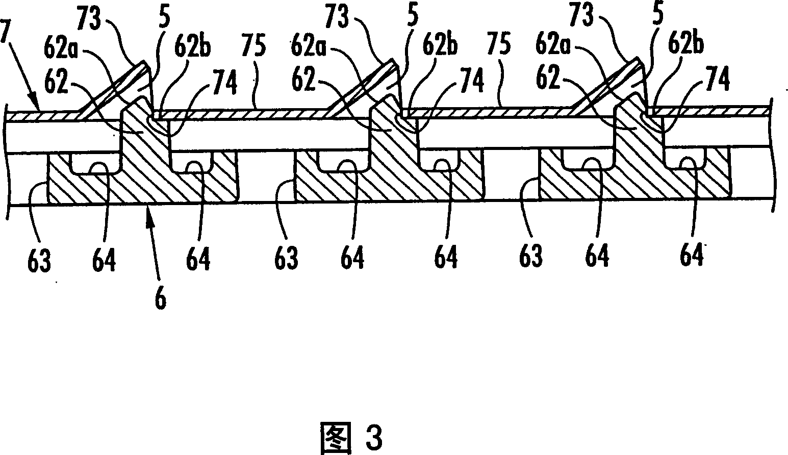
[0015] The burner ceiling 4 is composed of an annular lower plate member 6 placed on the burner body 1 , and an annular upper plate member 7 placed on the lower plate member 6 . The lower plate member 6 is a cast product, and a cylindrical portion 61 is vertically provided on the inner per...


PUM


Abstract

A burner for a stove. On the top of the burner top cover placed on the burner body, a plurality of radial flame holes (5) are formed at intervals in the circumferential direction. The lower plate member (6) and the upper plate The member (7) constitutes the top cover of the burner. On the lower plate member, a plurality of protrusions (62) protrude with intervals in the circumferential direction, and on the upper plate member, there are protrusions formed with each protrusion at intervals in the circumferential direction. A plurality of cutting upturned parts (73) forming each flame hole therebetween, and a plurality of communication holes (63) are opened in the part between the protrusions of the lower plate member, so that the gas passes through the communication holes and is guided to each In the flame hole, a depression (64) lower than the upper end of the hole edge of each communication hole is formed on the upper surface of the portion between the communication holes of the lower plate member, and a protrusion is protruded from the depression. The recessed portion serves as a receiving portion for the overflowing soup, thereby preventing the overflowing soup from flowing into the burner main body from the communication hole.

Description

technical field [0001] The present invention relates to a burner for a stove used in a gas stove, and in particular to a burner for a stove, that is, it has: The burner top cover of the distribution chamber is arranged on the top of the burner top cover: there are a plurality of radial flame holes at intervals in the circumferential direction, so that the gas flows from each Flame holes spew out. Background technique [0002] Conventionally, as such a burner for a stove, there is known a burner top cover composed of a lower plate member and an upper plate member placed on the lower plate member, and the lower plate member protrudes radially with intervals in the circumferential direction. There are provided a plurality of protruding lines protruding upward, and on the upper plate member, there are spaced apart in the circumferential direction and radially formed: a plurality of cutting warps facing the upper end surface of each projected line at intervals Each flame hole i...

Claims


Application Information

Patent Timeline
Patent Type & Authority Applications(China)
IPC IPC(8): F23D14/58
Inventor 赤木万之猪股匡顺
Owner RINNAI CORP
Why Eureka
Eureka Blog
Learn More