Method for differentiating electrical system oscillation and fault according to phase

A power system and fault technology, applied in the field of power system automation control, can solve the problems of false tripping of protection, improper setting, inability to correctly distinguish oscillation and fault, etc.

Inactive Publication Date: 2007-03-21
NARI TECH CO LTD
View PDF0 Cites 5 Cited by
  • Summary
  • Abstract
  • Description
  • Claims
  • Application Information

AI Technical Summary

Problems solved by technology

If the setting is not proper, it will be impossible to correctly distinguish

Method used


Image

  • Method for differentiating electrical system oscillation and fault according to phase
  • Method for differentiating electrical system oscillation and fault according to phase
  • Method for differentiating electrical system oscillation and fault according to phase

Examples


Embodiment Construction

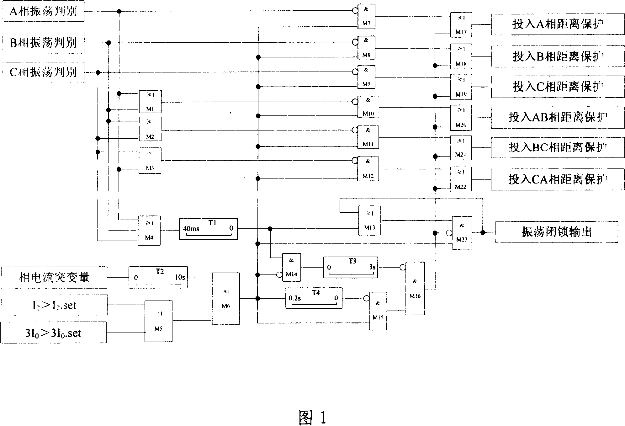
[0044] With reference to accompanying drawing 1, illustrate according to the control flow of the present invention, as follows:

[0045] As shown in the figure, the industry personnel can understand the method for distinguishing oscillation and fault according to the phase of the present invention through the accompanying drawing.

[0046] M1~M3: Indicates phase-to-phase output.

[0047] M4: Indicates that there is oscillation output.

[0048] T1: Mainly to avoid the impact of non-periodic components on oscillation measurement when faults occur.

[0049] M6: It is used to protect and start the component action output.

[0050] M14: M14 has output only when a fault occurs first and then oscillation occurs.

[0051] T3: Stretch the output signal of M14 for 3 seconds.

[0052] T4 and M15: jointly constitute the logic of opening 0.2 seconds after the action of the activation element.

[0053] M16: There is output within 0.2 seconds after the start element is activated and the...


PUM


Abstract

The invention discloses a method to divide the surge and the short circuit. It is based on the characteristic of the oscillating current envelope line in the electric power system. It finds the relation between the constant component Io and the alternate component Im in the condition of mishandling in the distance protection part because of the oscillating. When the Im >= k2Io, it is the oscillation; In the process of oscillation error, it finds the relation between the Io and the instantaneous component i, when the I >= k1Io, the angle between the power supply potential of the circuit sides is bigger than 75degreewhich is the second criterion. When it feeds the above two criterions, the surge and the short circuit will be divided. The invention can react with the mishandling in the distance protection part because of the oscillating and the short circuit; it is free from the influence that the electric power system circulates condition variety; and it doesn't limit to the system oscillating period, so it can reach the reliable lock by sensing the distance protection which is sensitive to the oscillation.

Description

technical field [0001] The present invention relates to an automatic control of electric power system, especially a method for distinguishing power system oscillation and fault Background technique [0002] In order to ensure the safe operation of the power system, necessary automatic protection devices, such as high-speed distance protection devices, must be equipped. In view of the fact that these protections cannot distinguish system oscillation or failure in principle, a dedicated oscillation blocking circuit must be provided. The working principle of the oscillating locking loop used in the past is: [0003] (1) Distinguish between oscillation and short circuit according to the principle of slow change in electrical quantity oscillation and rapid change in short circuit, such as using current elements or impedance elements with different sensitivities, or responding to sudden changes in current to control protection work. These different schemes have certain restricti...

Claims


Application Information

Patent Timeline
IPC IPC(8): G01R31/08H02H7/00H02H7/26H02H3/26
Inventor 许捷孟宪民侯喆
Owner NARI TECH CO LTD
Why Eureka
Try Eureka