Supercharge Your Innovation With Domain-Expert AI Agents!

Electromagnetic wave reception and decoding system provided with a compact antenna

An antenna, compact technology, applied in the field of compact antenna and decoder combination, can solve the problems of increased cost of portable antennas, increased number of accessories, etc., to achieve the effect of reduced size and high-quality reception

Inactive Publication Date: 2007-03-21
THOMSON LICENSING SA
View PDF0 Cites 4 Cited by
  • Summary
  • Abstract
  • Description
  • Claims
  • Application Information

AI Technical Summary

Problems solved by technology

[0019] However, it seems that the proposed modification has resulted in an increase in the cost of the portable antenna, as well as in the number of associated accessories

Method used


Image

  • Electromagnetic wave reception and decoding system provided with a compact antenna
  • Electromagnetic wave reception and decoding system provided with a compact antenna
  • Electromagnetic wave reception and decoding system provided with a compact antenna

Examples


Embodiment Construction

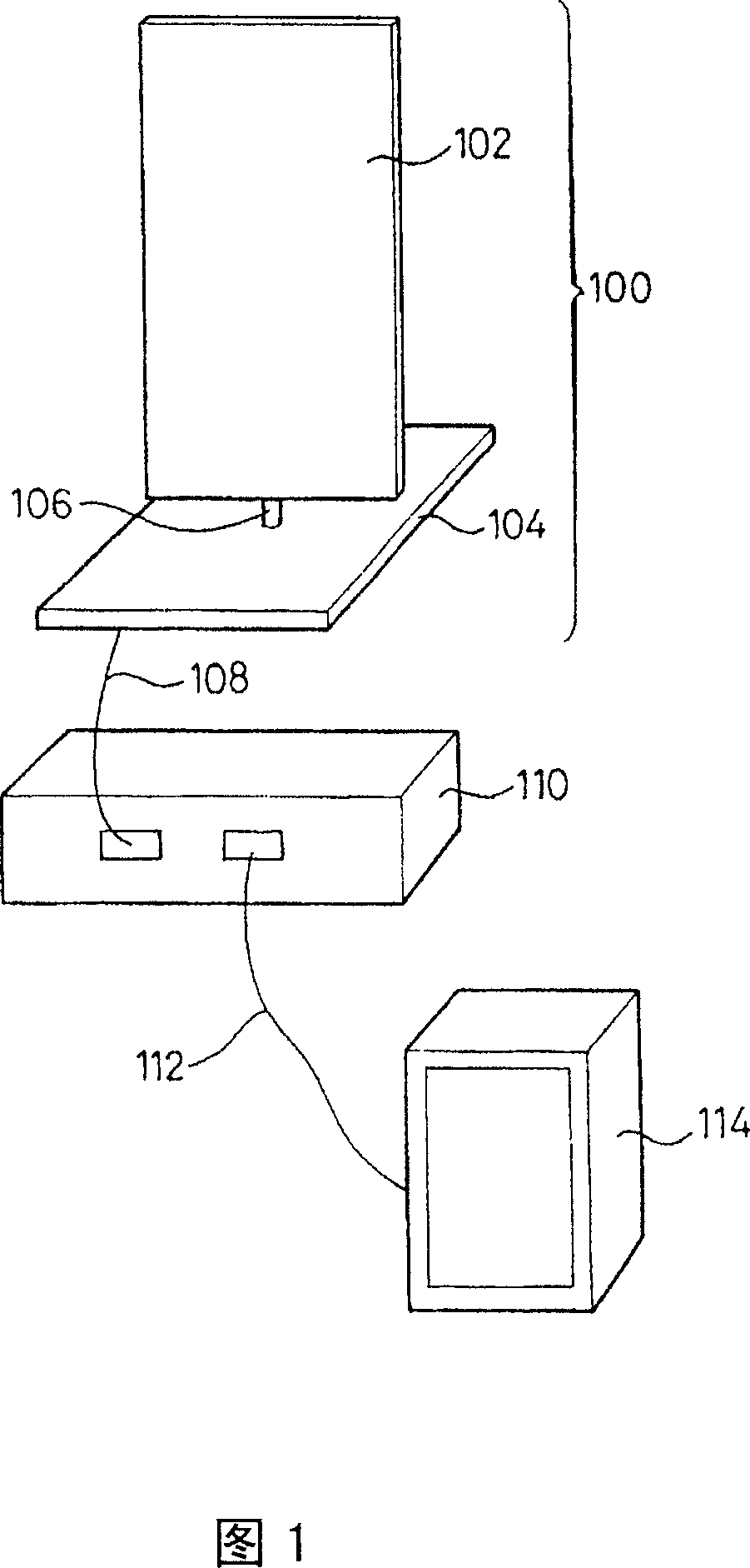
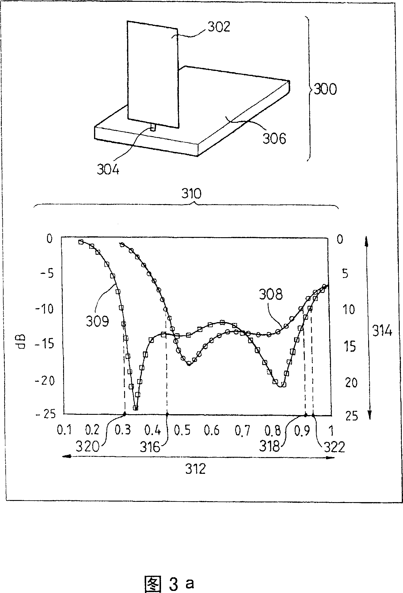
[0047] Figure 3a shows a monopole antenna 300 according to the invention operating in the frequency range whose center frequency corresponds to the wavelength λ, and a graph 310 of the reflection coefficient of said antenna 300.

[0048] The antenna 300 includes a radiation element 302 combined with a ground plane through a rod 304 . The rod 304 is located on an edge near the ground plane 306 . In this embodiment, the ground plane 306 has at least one of its dimensions, specifically length, width and / or height, on the order of a multiple of λ / 2.

[0049] The dimensions of the radiating element 302 are 175mm high and 90mm wide. The dimensions of the ground plane 306 are 250 mm by 150 mm.

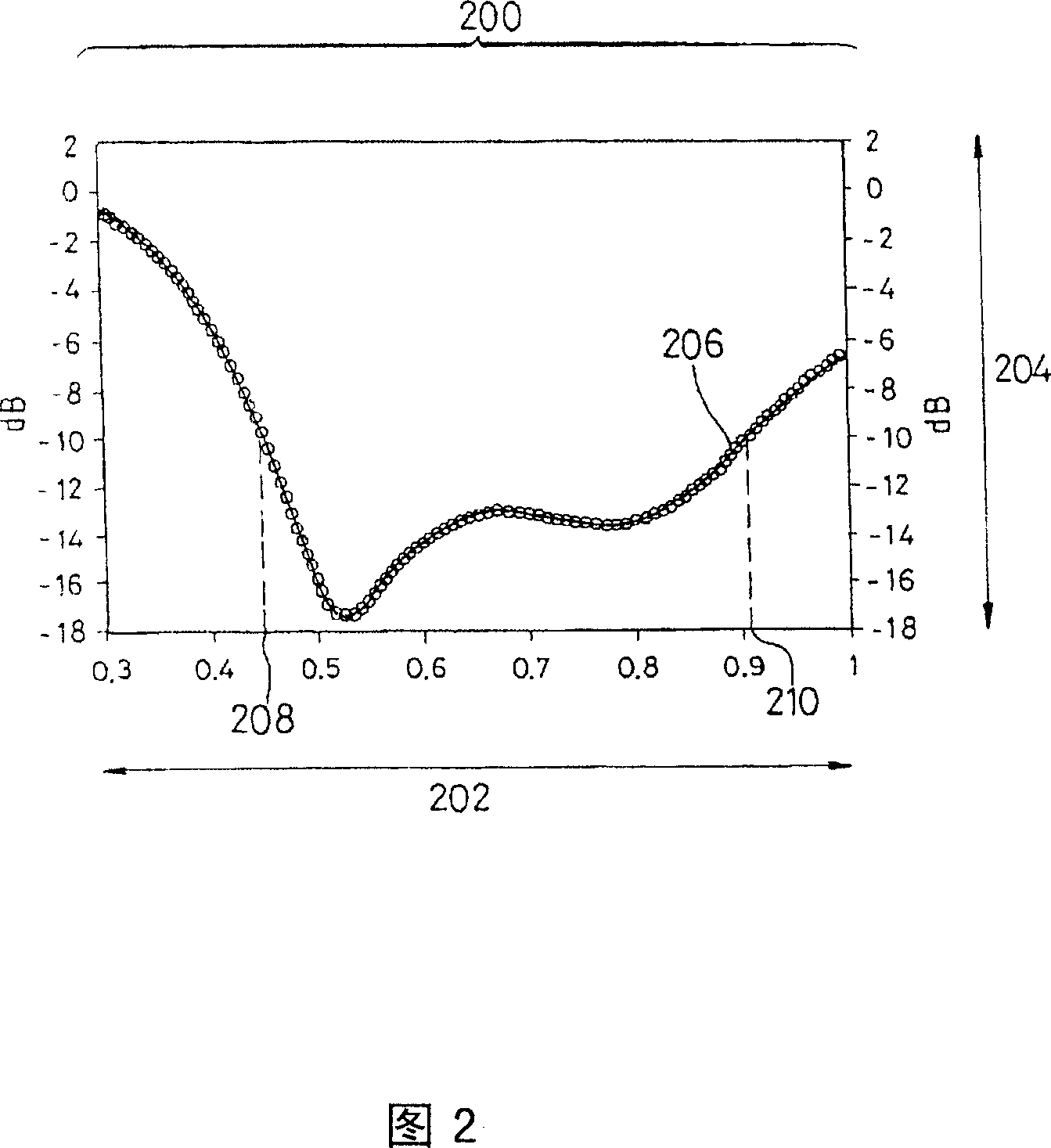
[0050] Graph 310 shows curve 308 corresponding to prior art antenna 100, and curve 309 corresponding to antenna 300 according to the present invention, said curves 308 and 309 representing as frequency (plotted on x-axis 312 as The change in reflection coefficient (plotted on the y-axis 31...


PUM


Abstract

The invention relates to a data transmission system comprising an antenna provided with a monopole radiating element held in place by an earth plane provided with a conducting surface. According to the invention, the radiating element is located facing the surface of the earth plane so as to interact with the latter in order to improve its performance.

Description

technical field [0001] The invention relates to a system for receiving and decoding electromagnetic waves with a compact antenna, in particular by combining such a compact antenna with a decoder in the field of digital terrestrial television. Background technique [0002] As the number of wireless information transmission methods increases, the use of antennas is becoming more and more widespread. In digital terrestrial television in particular, the use of antennas is expected to increase substantially in recent years due to the known advantages of digital modulation providing a wider range of television programming than analogue television. [0003] However, despite the robustness of the modulation used for digital terrestrial television, the measurement campaign showed substantial reception problems when portable antennas were used for reception. [0004] This is because the transmission signal of digital terrestrial TV is digital, which is different from the gradually de...

Claims


Application Information

Patent Timeline
Patent Type & Authority Applications(China)
IPC IPC(8): H01Q9/40H04B7/00
CPCH01Q9/40H04B7/00H01Q7/00H01Q21/24H01Q3/44H01Q1/24H01Q9/30
Inventor 让-弗朗索瓦·平托斯让-卢克·罗伯特菲利普·米纳德阿里·卢泽尔
Owner THOMSON LICENSING SA
Features
  • R&D
  • Intellectual Property
  • Life Sciences
  • Materials
  • Tech Scout
  • Unparalleled Data Quality
  • Higher Quality Content
  • 60% Fewer Hallucinations
Learn More