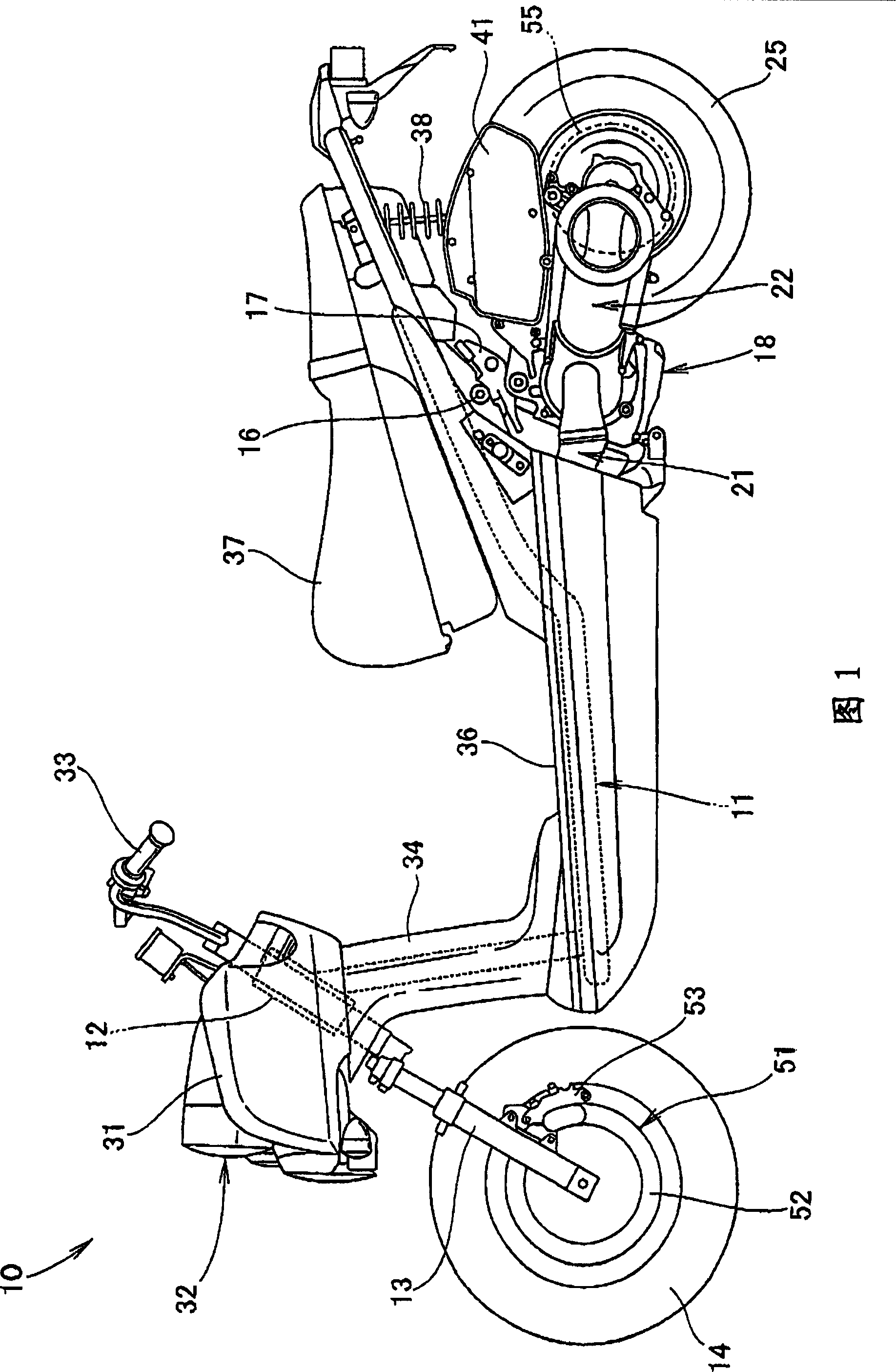
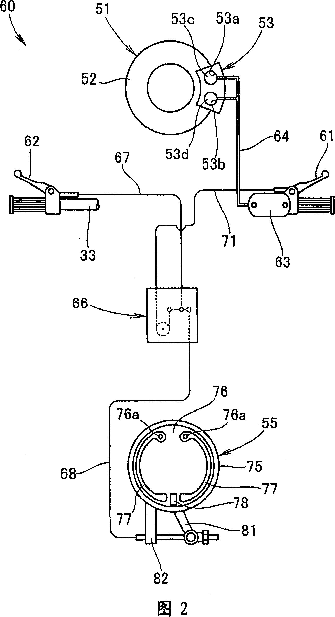
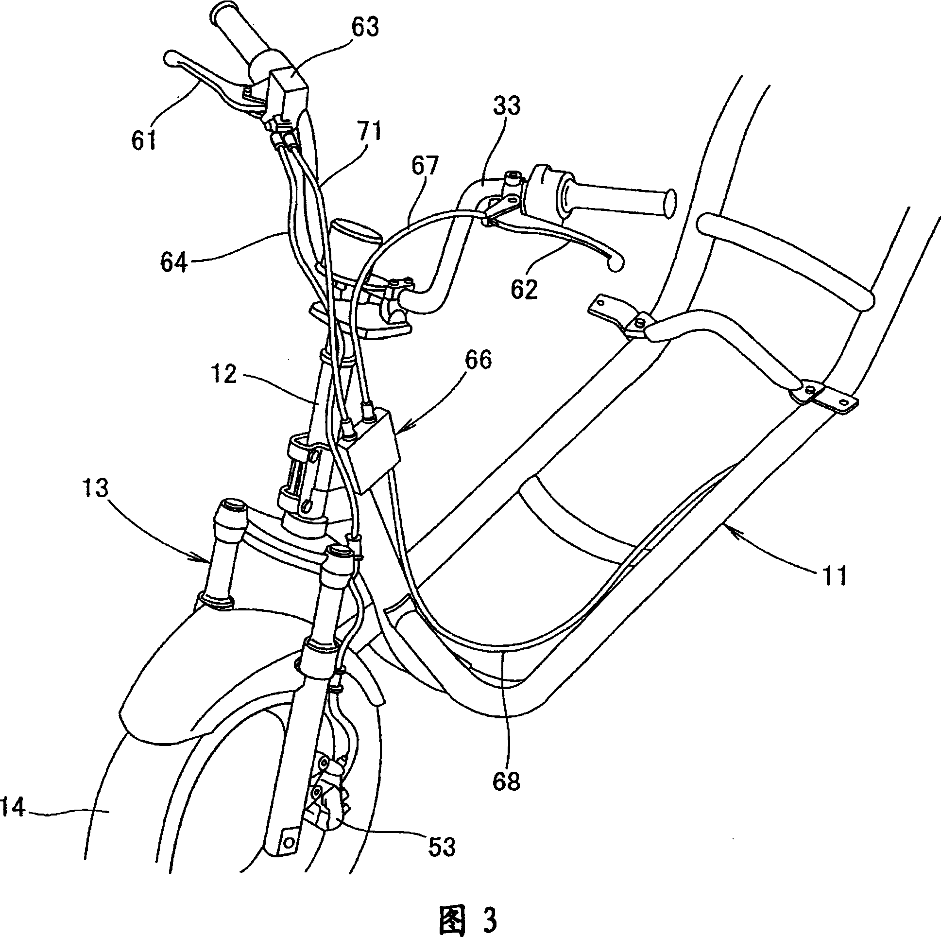
Braking device for vehicle
A braking device and vehicle technology, applied to bicycle brakes, bicycle accessories, etc., can solve problems such as large space, and achieve the effects of improving design freedom, improving transmission efficiency, and effectively using space
Inactive Publication Date: 2010-12-01
HONDA MOTOR CO LTD
View PDF1 Cites 1 Cited by
- Summary
- Abstract
- Description
- Claims
- Application Information
AI Technical Summary
Problems solved by technology
Because the front brake cable 34 cannot be bent with such a small curvature, a relatively large space is still required in order to change the direction of the front brake cable 34
Method used
View moreImage
Smart ImageViewing Examples
Examples
Embodiment Construction
Login to View More PUM
 Abstract
Provided is a brake device which does not require a large space in a vehicle. At midpoints of an input brake cable 67 and an output brake cable 68, an operation force distributing lever 102 stored in a casing 101 is interposed. An interlocking brake cable 71 is coupled to the operation force distributing lever 102 through a cable direction changing mechanism 131. A tip end of the interlocking brake cable 71 is coupled to a right brake lever, thereby changing a direction drawing the interlocking brake cable relative to a direction drawing the input brake cable 67 and the output brake cable 68.
Description
vehicle brakes technical field The present invention relates to improvements in braking devices for vehicles. Background technique In the braking device of the vehicle, there is such a braking device: a pair of left and right brake levers are arranged on the lever handle, and by operating one of the above two brake levers, for example, the front wheel is braked. Operate the other brake lever of the above two, for example, brake the rear wheel. There is also a linked brake device in which both the front wheel and the rear wheel can be braked by operating one of the brake levers in order to improve operability. As such a linkage-type conventional vehicle brake device, it is known that an operation force distribution lever for transmitting the operation force of the brake lever to the brakes on the front wheel side and the rear wheel side is arranged on the brake lever. A braking device in the vicinity of the rod (for example, refer to Japanese Patent Document 1.). [Pate...
Claims
Login to View More Application Information
Patent Timeline
 Patent Type & Authority Patents(China)
IPC IPC(8): B62L3/08B62L3/02
Inventor 出羽圭吾涩谷雅典须田知克
Owner HONDA MOTOR CO LTD
Features
- R&D
- Intellectual Property
- Life Sciences
- Materials
- Tech Scout
- Unparalleled Data Quality
- Higher Quality Content
- 60% Fewer Hallucinations
Learn More Browse by: Latest US Patents, China's latest patents, Technical Efficacy Thesaurus, Application Domain, Technology Topic, Popular Technical Reports.
© 2025 PatSnap. All rights reserved.Legal|Privacy policy|Modern Slavery Act Transparency Statement|Sitemap|About US| Contact US: help@patsnap.com


