Jig mounting apparatus
A technology of installation devices and fixtures, applied in installation, measurement devices, manufacturing tools, etc., can solve problems such as inability to judge, and achieve the effect of clear detection
- Summary
- Abstract
- Description
- Claims
- Application Information
AI Technical Summary
Problems solved by technology
Method used
Image
Examples
Embodiment 1
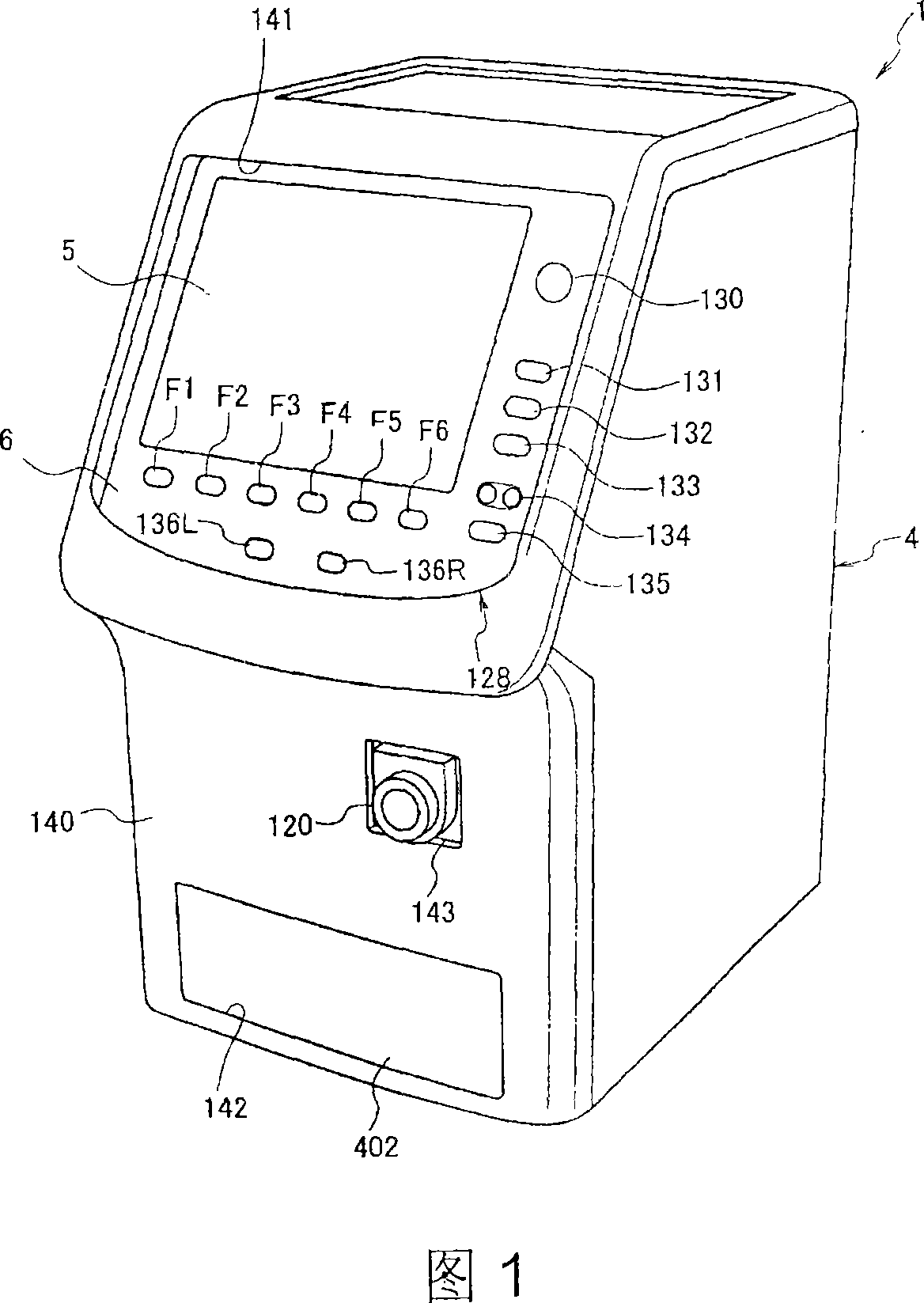
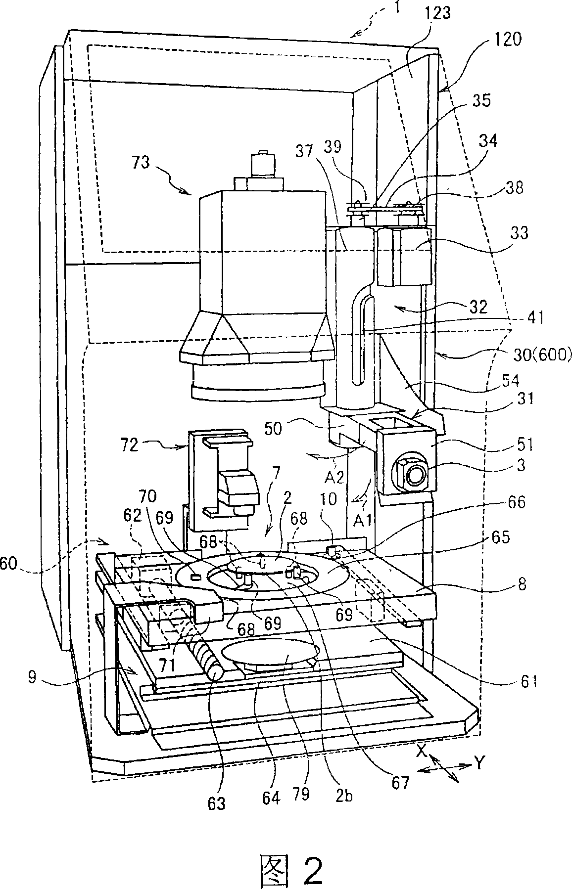
[0090] 1 and 2 show an embodiment of a clamp installation device 1 of the present invention. The jig installation device 1 in this embodiment accurately installs a jig 3 for processing a lens, especially a spectacle lens 2, on the spectacle lens 2 (refer to FIG. 2 ). As shown in FIG. 1 , the jig installation device 1 includes a housing 4 , a liquid crystal display unit 5 , and an operation key unit 6 .
[0091] As shown in FIG. 2 , the jig installation device 1 includes a support device for a spectacle lens 2 disposed inside a casing 2 . In the illustrated embodiment, the supporting device includes: a fixed plate 7 for placing unprocessed spectacle lenses 2; a platform 8 on which the fixed plate 7 is placed; a driving mechanism for driving the platform 8 in X and Y directions 9 ; and a drive mechanism 10 for driving the fixed plate 7 to rotate relative to the platform 8 .
[0092] The spectacle lens 2 includes: a printed mark 20 printed on its surface 2a, an identification m...
example 2
[0266] As shown in FIG. 31 , when the interchangeable frame lens holder 570 is installed on the ring gear 551 , the images shown in FIGS. 50 to 53 are displayed on the liquid crystal display 129 . In FIGS. 50 to 53 , reference numeral 950 denotes an arm image of the lens holding arm 66 , and reference numeral 952 denotes a cutout area. In Fig. 51, reference numeral 951 denotes the lens shape of the interchangeable frame lens holder shown in Figs. 30 and 31 .
[0267] Next, referring to FIG. 54 , the processing of Example 2 for checking the presence or absence of spectacle lenses will be described below.
[0268] (step S11)
[0269] The operation control circuit 100 receives the image signal from the CCD 115, starts the process of judging whether there is a lens shown in FIG.
[0270] That is, the arithmetic control circuit 100 sets the cutout area 952 (processing area) indicated by the square frame in FIG. 50, and proceeds to step S12. The cut-out area 952 is set approximat...
PUM
 Abstract
Description
Claims
Application Information
 - R&D Engineer
- R&D Manager
- IP Professional
- Industry Leading Data Capabilities
- Powerful AI technology
- Patent DNA Extraction
Browse by: Latest US Patents, China's latest patents, Technical Efficacy Thesaurus, Application Domain, Technology Topic, Popular Technical Reports.
© 2024 PatSnap. All rights reserved.Legal|Privacy policy|Modern Slavery Act Transparency Statement|Sitemap|About US| Contact US: help@patsnap.com


