High-pressure by-pass valve

A technology of bypass valve and bypass channel, which is applied to multi-way valves, valve devices, engine components, etc., can solve problems such as poor stability, high noise, and large vibration, and achieve reduced vibration, safe and reliable work, and stable work Effect

Inactive Publication Date: 2007-04-04
黄作兴
View PDF0 Cites 7 Cited by
  • Summary
  • Abstract
  • Description
  • Claims
  • Application Information

AI Technical Summary

Problems solved by technology

However, because the valve closes instantaneously when a fault occurs, the existing high-pressure bypass valve has the defects of high noise, large vibration, and poor stability

Method used


Image

  • High-pressure by-pass valve
  • High-pressure by-pass valve
  • High-pressure by-pass valve

Examples


Embodiment Construction

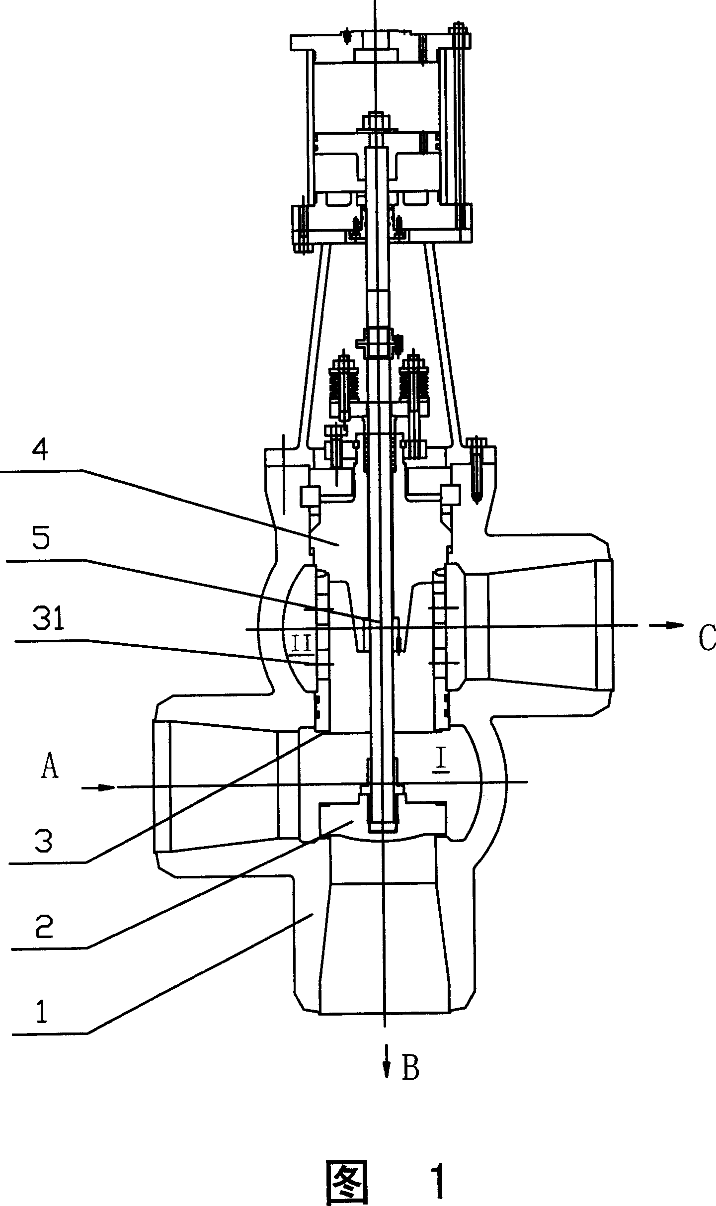
[0014] As shown in Fig. 1, the figure is a cross-sectional view of the high pressure bypass valve of the present invention. The valve includes a valve body 1, on which two connected chambers are formed, wherein the chamber I is the main channel chamber, and the chamber includes an inlet A and an outlet B, which are used as high-pressure bypass inlets When the valve is used, the inlet A is connected to the water inlet pipe, and the outlet B is connected to the inlet of the high pressure heater. A passageway chamber, which communicates with the main passageway chamber, and has a bypass port C, which is connected with a bypass passageway.

[0015] A disc 2 can move up and down in the longitudinal direction of the valve body 1, and when it is in the highest position, it will separate the bypass passage chamber from the main passage chamber and open the main passage; when it is in the lowest position, it will open the main passage. closed, the chamber of the bypass channel communi...


PUM


Abstract

The invention comprises a valve body and main and bypass channel cavities formed on the valve body. The main channel cavity includes an inlet and an outlet and the bypass channel cavity has an outlet. A valve clack following a valve stem moves longitudinally in the valve body. In the bypass channel cavity is disposed a cage-type valve seat with several throttle orifices on the cylinder wall of the valve clack. At the bottom of the valve seat is disposed a seal seat fit with the valve clack and on the top of the valve seat is fixed a valve cover. The valve extends through the valve cover.

Description

technical field [0001] The invention relates to a valve, in particular to a high-pressure bypass valve. Background technique [0002] Usually, the high-pressure bypass valve is used in power plants and used in conjunction with the steam turbine; specifically, it is installed at the inlet and outlet of the high-pressure heater in the boiler feed water system to serve as the high-pressure bypass inlet valve and the high-pressure bypass outlet respectively valve. In normal operation, the discs of the inlet valve and the outlet valve are at the upper end, water enters downward from the inlet of the inlet valve, and enters the heater through the main channel. When the high-pressure heater fails, the valve clack quickly closes the main channel and opens the bypass pipeline of the high-pressure heating system, and the water flows to the bypass without entering the high-pressure heater, but directly enters the boiler through the bypass system. However, because the valve closes ins...

Claims


Application Information

Patent Timeline
Patent Type & Authority Applications(China)
IPC IPC(8): F16K11/044
Inventor 黄作兴
Owner 黄作兴
Why Eureka
Try Eureka