Motor

A motor and hollow core technology, applied in the field of motors, can solve the problems of uneven pressure, breakage, uneven pressure of the winding end 105b, etc.

Inactive Publication Date: 2007-04-04
SANKYO SEIKI MFG CO LTD
View PDF1 Cites 1 Cited by
  • Summary
  • Abstract
  • Description
  • Claims
  • Application Information

AI Technical Summary

Problems solved by technology

[0008] Therefore, when the coil wire 105 is assembled into the inner stator core 102a, the wire end 105b on the end face 105a of the coil wire 105 is compressed between the coil wire 105 and the inner stator core 102a, so that the The wire end 105b is subjected to uneven pressure (load), and there is a possibility of breaking
[0009] In addition, even after the coil wire 105 is assembled into the inner stator core 102a, the wire end 105b may be subjected to uneven pressure ( load), so that the wire end 105b breaks between the coil wire 105 and the inner stator core 102a, etc.

Method used


Image

  • Motor
  • Motor
  • Motor

Examples


Embodiment Construction

[0062] Hereinafter, an example of a motor to which the present invention is applied will be described with reference to the drawings.

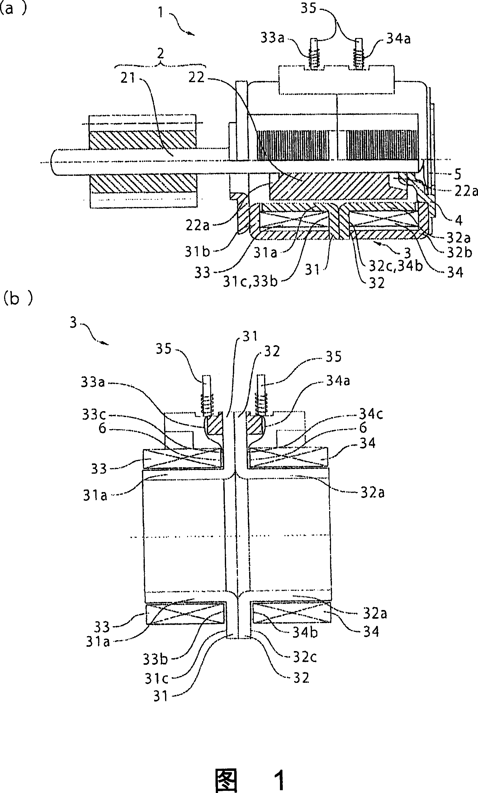
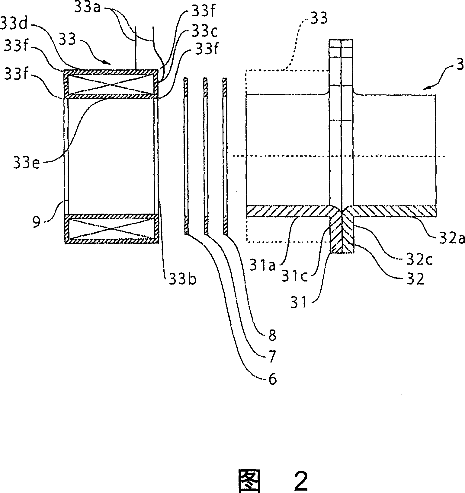
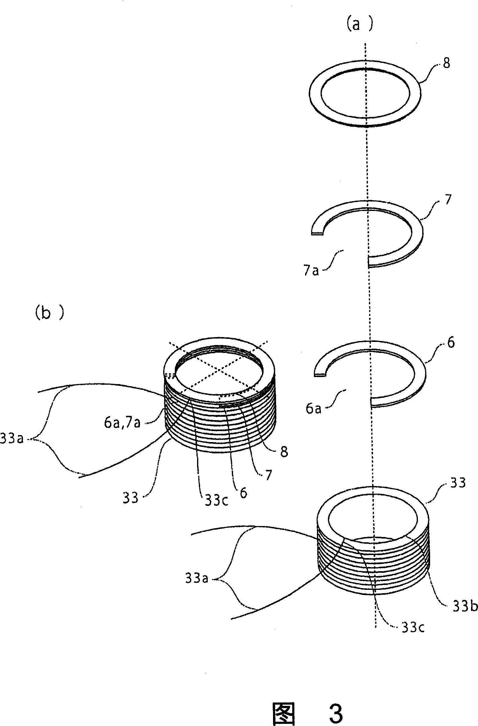
[0063] Fig. 1(a) is a sectional view of a main part of a motor to which the present invention is applied. FIG. 1( b ) is a cross-sectional view showing the structure of a part of the stator of the motor shown in FIG. 1( a ). FIG. 2 is an exploded explanatory diagram illustrating the disassembled structure of the stator of the motor shown in FIG. 1( a ) and FIG. 1( b ). Fig. 3(a) is an exploded perspective view viewed obliquely from above after decomposing the air-core coil, disconnection preventing member, adhesive layer, and insulating sheet in the structure of the stator shown in Fig. 2 . Fig. 3(b) is an assembled view after integrally assembling the air-core coil shown in Fig. 3(a), the disconnection preventing member, the adhesive layer, and the insulating sheet.

[0064] (the overall structure of the motor)

[0065] As shown in Fig. 1 ...


PUM


Abstract

The present invention provides a motor for overcoming a problem that windings are disconnected when a pressure (load) is applied to the windings in air core coils. A disconnection preventing member (6) is provided, and formed with an escaping section (6a) for escaping the winding (33a) in a drawing section (33c) of the air core coils (33, 34) between end faces of stator cores (31, 32) and the air core coils (33, 34). Since the windings (33a, 34a) located in the drawing section (33c) of the air core coils (33, 34) are drawn from the escaping section of the disconnection preventing member (6) when the air core coils (33, 34) are fitted into the stator cores (31, 32), the problem that the windings (33a, 34a) are compressed between the end faces of the stator cores (31, 32) and the air core coils (33, 34), the nonuniform pressure (load) is applied and the disconnection occurrence can be overcomed.

Description

technical field [0001] The invention relates to an electric motor. In particular, it relates to preventing breakage of winding wires of air core coils. Background technique [0002] As shown in Figure 6, the stepper motor used in digital cameras, digital video cameras, FDD, ODD, etc. generally includes: a rotor 201 with a magnet fixed to a rotating shaft, a stator 202 arranged opposite to the rotor 201, a circular An annular bobbin 204 and a coil wire 205 wound around a cylindrical portion of the bobbin 204 . [0003] In the stepping motor 200 having such a structure, in order to realize the miniaturization of the motor body, the bobbin 204 is integrally formed on the inner stator core 202a constituting the stator 202 by insert molding, so that the stepping motor 200 can be miniaturized. . [0004] However, even in the stepping motor 200 in which the bobbin 204 is integrally formed on the inner stator core 202a, the occupancy ratio of the bobbin 204 increases as the size ...

Claims


Application Information

Patent Timeline
Patent Type & Authority Applications(China)
IPC IPC(8): H02K37/14H02K15/04
Inventor 内海信一
Owner SANKYO SEIKI MFG CO LTD
Why Eureka
Try Eureka