Annular component fabricating method, die for use in such fabricating method and annular component fabricated thereby

A technology of ring-shaped parts and ring-shaped recesses, which is applied in the manufacturing field of ring-shaped parts, can solve the problems of increased production process space or surface area in the middle of inventory costs, decreased productivity, and difficulty in shortening delivery dates, etc., to achieve shortened processing time, Productivity improvement and equipment cost reduction effects

Inactive Publication Date: 2007-04-11
DENSO CORP
View PDF3 Cites 25 Cited by
  • Summary
  • Abstract
  • Description
  • Claims
  • Application Information

AI Technical Summary

Problems solved by technology

Another concern includes inventory costs, increased space or surface area necessary for intermediate production processes
In addition, although the product structure is simple, it still leads to a decrease in productivity, and it is difficult to shorten the delivery date

Method used


Image

  • Annular component fabricating method, die for use in such fabricating method and annular component fabricated thereby
  • Annular component fabricating method, die for use in such fabricating method and annular component fabricated thereby
  • Annular component fabricating method, die for use in such fabricating method and annular component fabricated thereby

Examples


no. 1 example

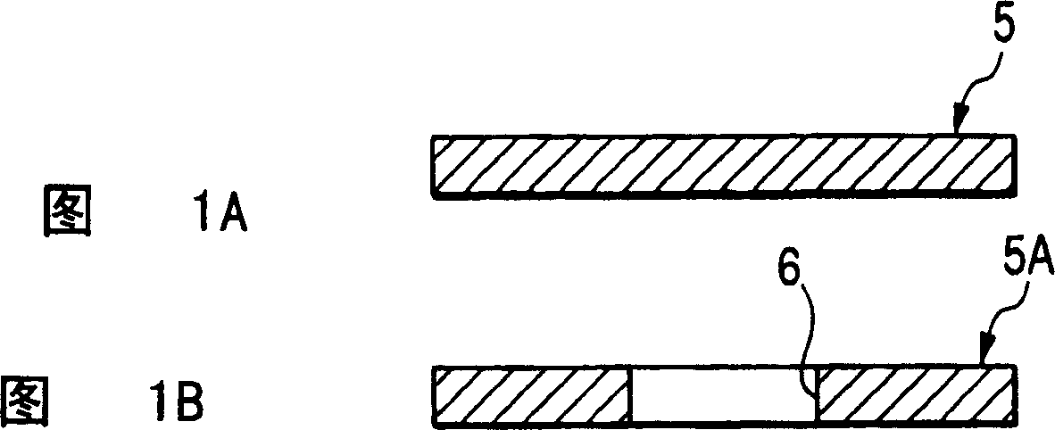
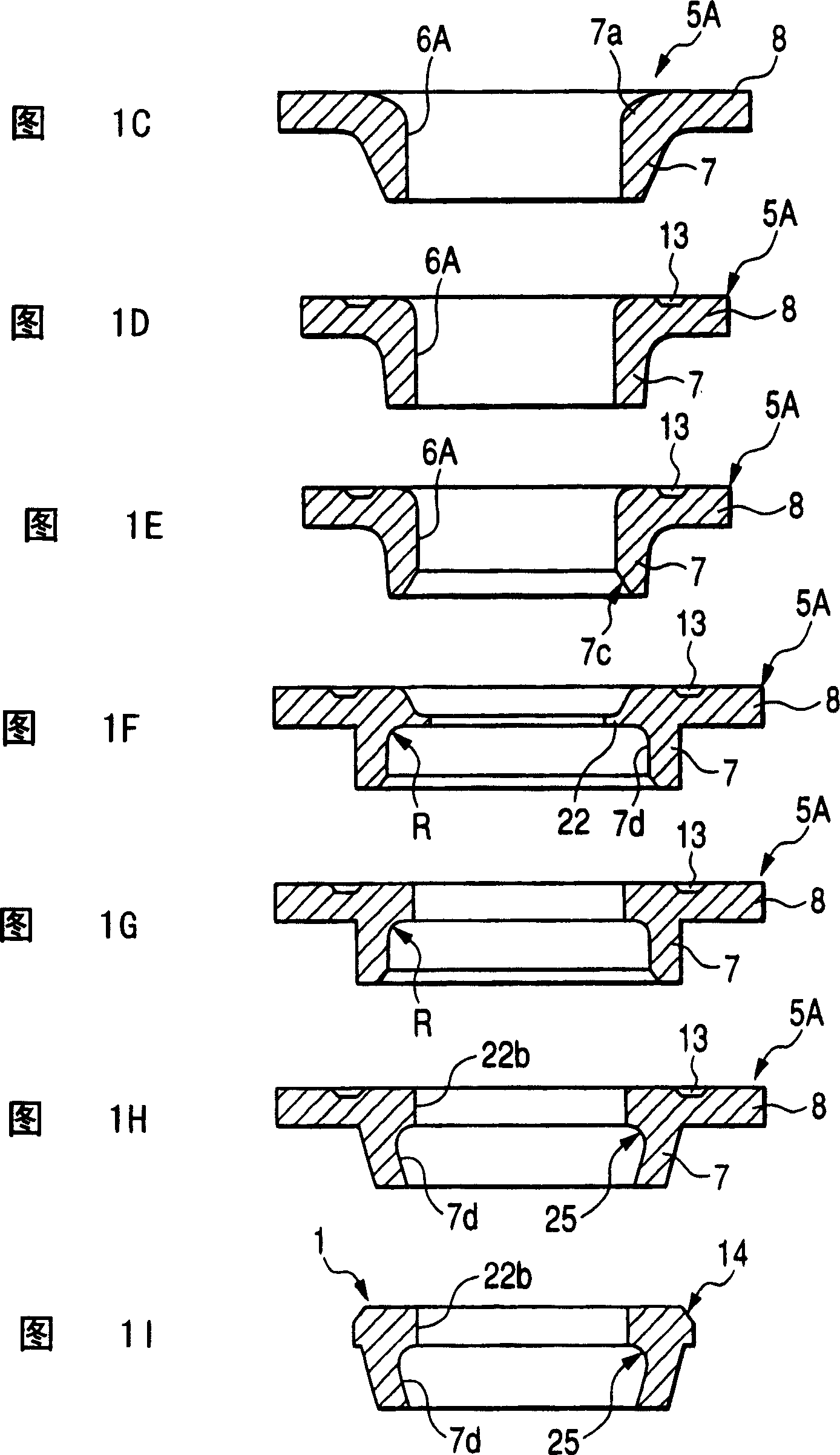
[0080] 1A-1I show flow charts for carrying out the method of manufacturing the annular component 1 .

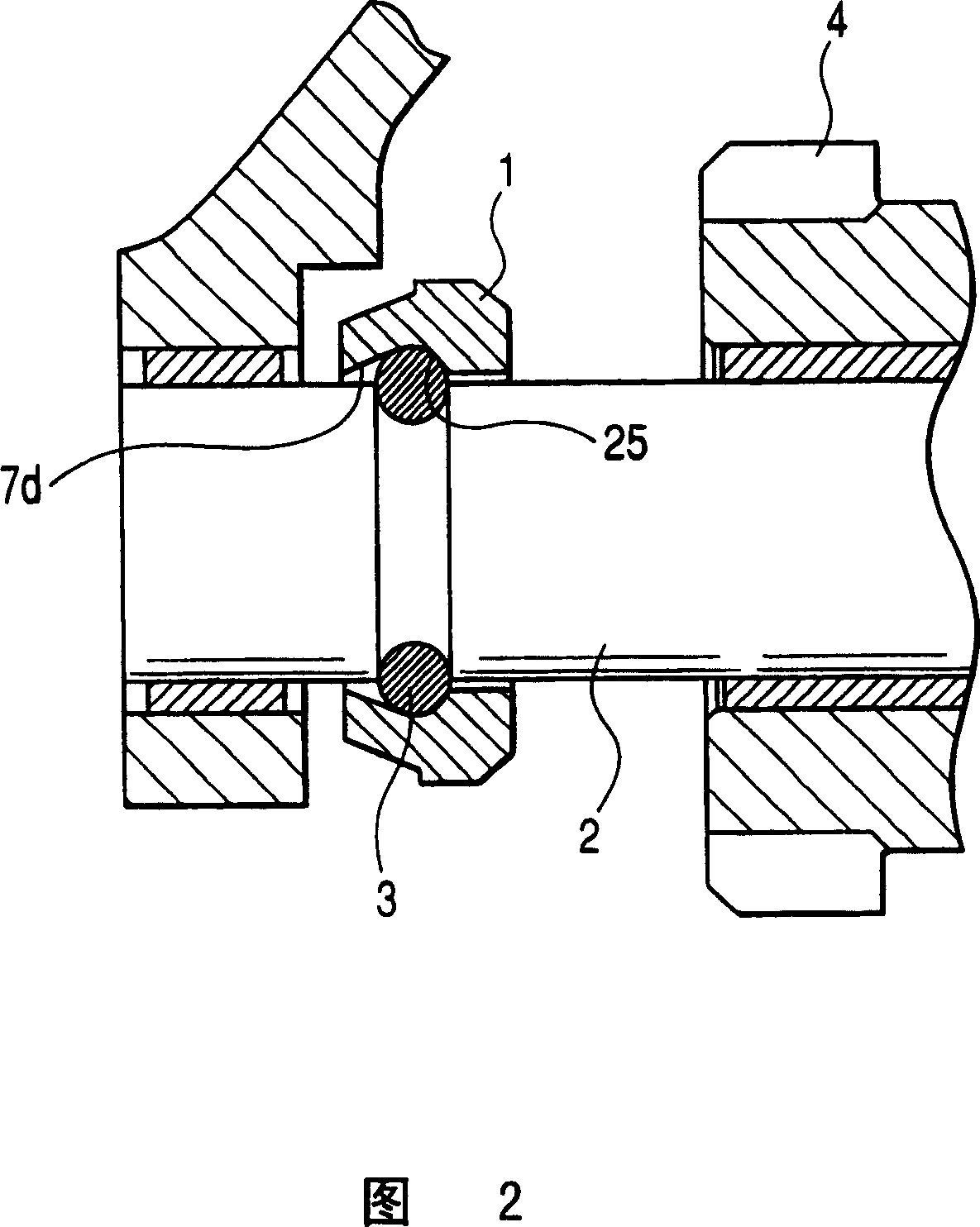
[0081] As shown in FIG. 2 , the annular member 1 of the first embodiment performs, for example, the function of a stop ring 1 which is mounted on the engine starting ring 3 by means of a snap ring 3 fitted to the outer circumference of the output shaft 2 . on output shaft 2 of the starter. The output shaft 2 carries thereon a slidable pinion 4 which is movable towards (to the left in FIG. 2 ) a ring gear (not shown) of the engine. The stop ring 1 is used as a movement limiting element, which limits the position in which the pinion 4 can move in the axial direction.

[0082] Now, a method of manufacturing an annular component 1 according to an embodiment of the present invention will be described with reference to FIGS. 1A-1I and FIGS. 3-10 . Figures 3, 5, 7 and 9 show the states in which the relevant upper dies are lifted upward when the respective processing is completed. ...

no. 2 example

[0130] Fig. 11 is a cross-sectional view of an annular member 1 (stop ring) obtained by the annular member manufacturing method according to the second embodiment of the present invention.

[0131] Although in the first embodiment, the extruding operation is performed using the tapered extruding punch 24 as shown in FIG. 9 , the second embodiment is characterized in that the extruding operation is performed using the roller 26 as shown in FIG. 11 . That is, the roller 26 held in an abutting engagement relationship with the outer peripheral wall 7b of the cylindrical wall 7 of the workpiece 5A rotates to cause the cylindrical wall 7 to gradually deform into a tapered shape.

[0132] Also, the second embodiment has the same steps as the first embodiment except for the pressing operation. Even with the method of the second embodiment, it is not necessary to use a cutting process to form the inner diameter recess 25 constituting the cut groove. In addition, the manufacturing meth...


PUM


Abstract

A method of fabricating an annular component part 1 is disclosed wherein press forming is carried out to prepare an annular body 5A having a cylindrical wall 7, having a root portion and a distal end, and an annular flange portion 8. The fabricating method comprises expanding an inner circumferential periphery 7d of the cylindrical wall 7 to an inner diameter corresponding to an inner diametric concave portion 25 formed on the inner circumferential periphery 7d and squeezing the cylindrical wall 7 in a tapered profile such that the inner diameter 7d of the cylindrical wall 7 gradually decreases. During inner diametric expanding operation, an annular shoulder 7e is formed on the inner circumferential periphery 7d of the cylindrical wall 7 and plays a role as an undercut of the annular component 1.

Description

[0001] Cross References to Related Applications [0002] This application is related to Japanese Patent Applications No. 2005-292627 and No. 2006-197249 filed on October 5, 2005 and July 19, 2006, respectively, the contents of which are incorporated herein by reference. technical field [0003] The present invention relates to a method for the manufacture of an annular part, more particularly, a method for manufacturing an annular part which performs the function of a stop ring mountable on the output shaft of a starter for engine starting , and the mold used in this manufacturing method and the ring-shaped part manufactured by this manufacturing method. Background technique [0004] In the prior art, as shown in Figure 14, the starter has an output shaft 100 slidably carrying thereon a pinion 110 which moves to mesh with a ring gear (not shown) of the engine. With this starter, as disclosed in Japanese Patent Examined Publication No. 6-78746, for the purpose of restricting...

Claims


Application Information

Patent Timeline
Patent Type & Authority Applications(China)
IPC IPC(8): B23P13/00B21D22/02B21C23/02B21J5/06B21D28/02B21K1/00B21D37/10B21C25/02B21J13/02
Inventor 高田雅广秀岛保广
Owner DENSO CORP
Why Eureka
Try Eureka