Optical sheet, backlight, and liquid crystal display device

A technology of optical sheets and cylindrical lenses, applied in lighting and heating equipment, optics, optical components, etc., can solve the problems of enhancing the side brightness of liquid crystal panels, deterioration of polarized light separation characteristics, and no contribution to brightness enhancement, etc., to achieve enhanced Effects of display brightness, improvement of directionality, enhancement of frontal brightness

Active Publication Date: 2007-04-11
SONY CORP
View PDF1 Cites 10 Cited by
  • Summary
  • Abstract
  • Description
  • Claims
  • Application Information

AI Technical Summary

Problems solved by technology

The second-order transmitted light component T2 is the luminous flux component emitted to the wide-angle side outside the effective angle field of view of the liquid crystal panel, and does not contribute to the enhancement of brightness
[0009] In addition, depending on the angle-dependent characteristics of the polarized light separation sheet arranged on the subsequent stage, polarized light separation characteristics are sometimes extremely deteriorated due to the directionality of incident light, which becomes an obstacle to effectively enhance the brightness of the liquid crystal panel side
[0010] In addition, in the case where the above-mentioned prism sheet is interposed between the diffuser and the liquid crystal panel, a blurred appearance occurs

Method used


Image

  • Optical sheet, backlight, and liquid crystal display device
  • Optical sheet, backlight, and liquid crystal display device
  • Optical sheet, backlight, and liquid crystal display device

Examples


example 1

[0184] (R=5, K=-2)

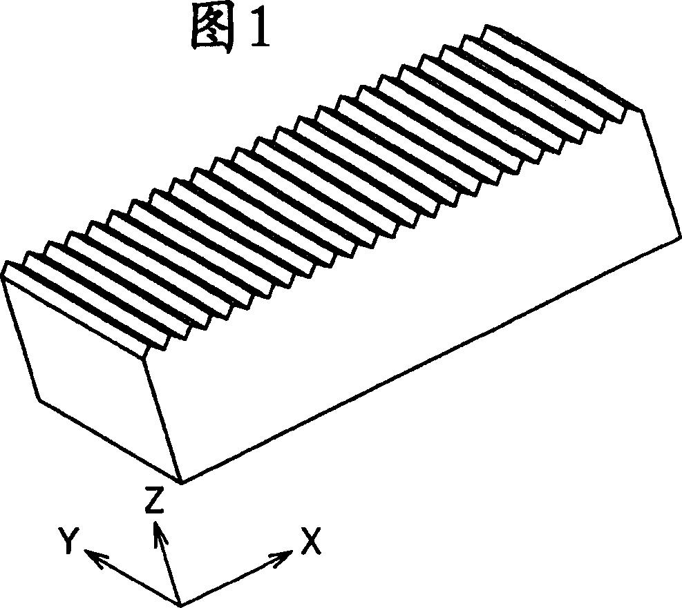
[0185] FIG. 9 shows the XZ cross section of the lens sheet of Working Example 1 on an enlarged scale. On the surface on the lens sheet, a large number of cylindrical lens elements having a finite focal length on the emission side of the illumination light and having left-right symmetrical hyperboloid surfaces are successively arranged. The hyperbolic surface is obtained by substituting K=-2 and R=5 into the expression (1) given above Z = X 2 / ( 5 + ( 25 + X 2 ) ) express.

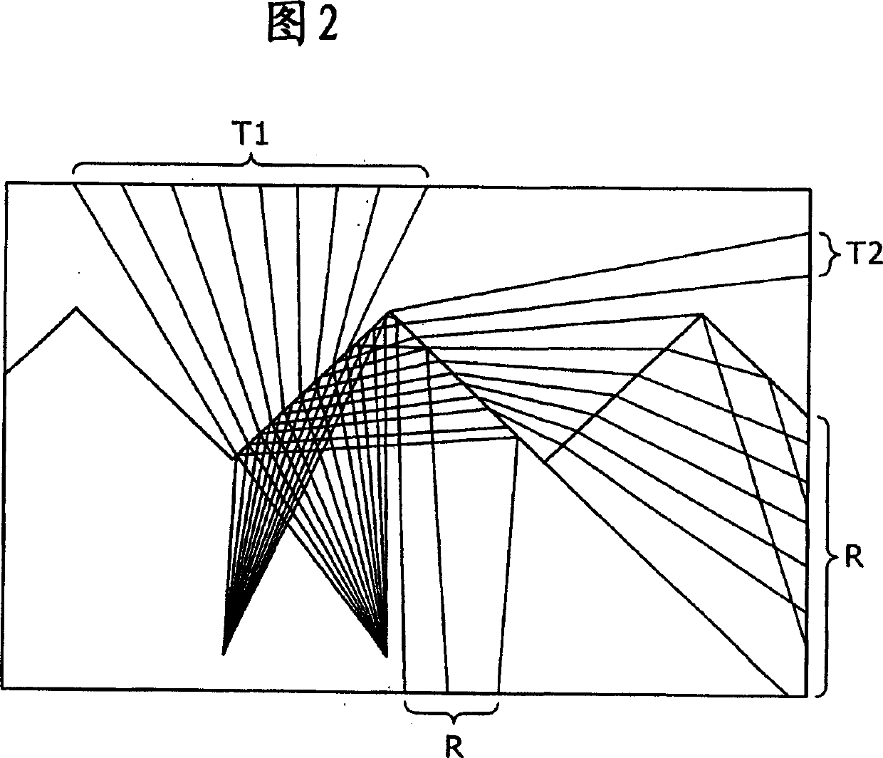
[0186] In the lens sheet shown in FIG. 9 , the light of the luminous flux Ω emitted from the virtual light starting point O directly below the apex of the hyperboloid surface and reaching the AB pl...

example 2

[0199] (R=5, K=-3)

[0200] FIG. 11 shows the shape of the XZ cross-section of the lens sheet on an enlarged scale. On the surface of the lens sheet are successively arranged cylindrical lens elements having a finite focal length on the emission side of the illumination light and having left-right symmetrical hyperboloid surfaces. The hyperbolic surface is obtained by substituting K=-3 and R=5 into the expression (1) given above Z = X 2 / ( 5 + ( 25 + 2 X 2 ) ) express.

[0201] Since it can be seen from FIG. 11 that the angle at which the asymptotes intersect each other expands compared to the lens sheet of FIG. 9 , the refracted transmitted lig...

example 3

[0205] (R=1, K=-2)

[0206] FIG. 13 shows the shape of the XZ cross-section of the lens sheet of Working Example 3 on an enlarged scale. On the surface of the lens sheet are successively arranged cylindrical lens elements having a finite focal length on the emission side of the illumination light and having left-right symmetrical hyperboloid surfaces. The hyperbolic surface is obtained by substituting K=-2 and R=1 into expression (1) Z = X 2 / ( 1 + ( 1 + X 2 ) ) express.

[0207] As can be seen from Fig. 13, the luminous flux Ω is refracted forward by the lens sheet and transmitted. The luminous flux Ψ is mostly totally reflected and then returned by refraction or total reflection by the...


PUM

PropertyMeasurementUnit
hardnessaaaaaaaaaa
thicknessaaaaaaaaaa
thicknessaaaaaaaaaa

Abstract

Cylindrical lens bodies are arrayed on one main surface of an optical sheet, and the lenses each have one finite focal length on the exit side of illumination light and have a left-right symmetrical hyperboloid or a paraboloid. The cross-sectional shape of each cylindrical lens body satisfies Z = X2 / (R + v(R2 - (1 + K)X2)) with the Z-axis in parallel with the direction normal to the optical sheet and the X-axis in the direction of the array of the cylindrical lens bodies, where R is the curvature radius of the vertex of the body and K is the conic constant.

Description

technical field [0001] The present invention relates to an optical sheet for enhancing the directivity of light, and a backlight device and a liquid crystal display device including the optical sheet. Background technique [0002] In recent years, for a liquid crystal display device including a liquid crystal panel, it is a very important subject to increase the brightness of the display while reducing power consumption to increase the commercial value of the liquid crystal display device. In such a case as just described, it is highly desirable to increase the optical gain on the side of the backlight device. Therefore, as a method of satisfying this requirement, it has been proposed to provide a liquid crystal display device having a prism sheet containing a prism array on the side from which illumination light is emitted (see, for example, Japanese Patent No. 3147205). [0003] Figure 1 shows the appearance of a traditional prism sheet. Fig. 2 shows the XZ cross-section...

Claims


Application Information

Patent Timeline
Patent Type & Authority Applications(China)
IPC IPC(8): G02B3/06G02B5/02F21S2/00G02F1/13357F21V5/04F21Y103/00G02B3/00F21Y101/00G02F1/1335
CPCG02F2001/133607G02F1/133606G02B5/0215G02B5/0278G02B5/0221G02B3/06G02B5/0294G02F1/133607G02B3/00G02B5/02G02F1/1335
Inventor 有马光雄清水纯小田桐广和太田荣治小幡庆
Owner SONY CORP
Why Eureka
Try Eureka