Driving device and method for display

A driving device and display technology, applied to static indicators, instruments, etc., can solve problems such as data collection errors and timing differences

Inactive Publication Date: 2007-04-18
ELAN MICROELECTRONICS CORPORATION
View PDF0 Cites 0 Cited by
  • Summary
  • Abstract
  • Description
  • Claims
  • Application Information

AI Technical Summary

Problems solved by technology

However, as the frequency increases, the probability of signal demodulation error also increases, because the setup time and hold time of the signal decrease with the increase of fr

Method used


Image

  • Driving device and method for display
  • Driving device and method for display
  • Driving device and method for display

Examples


Embodiment Construction

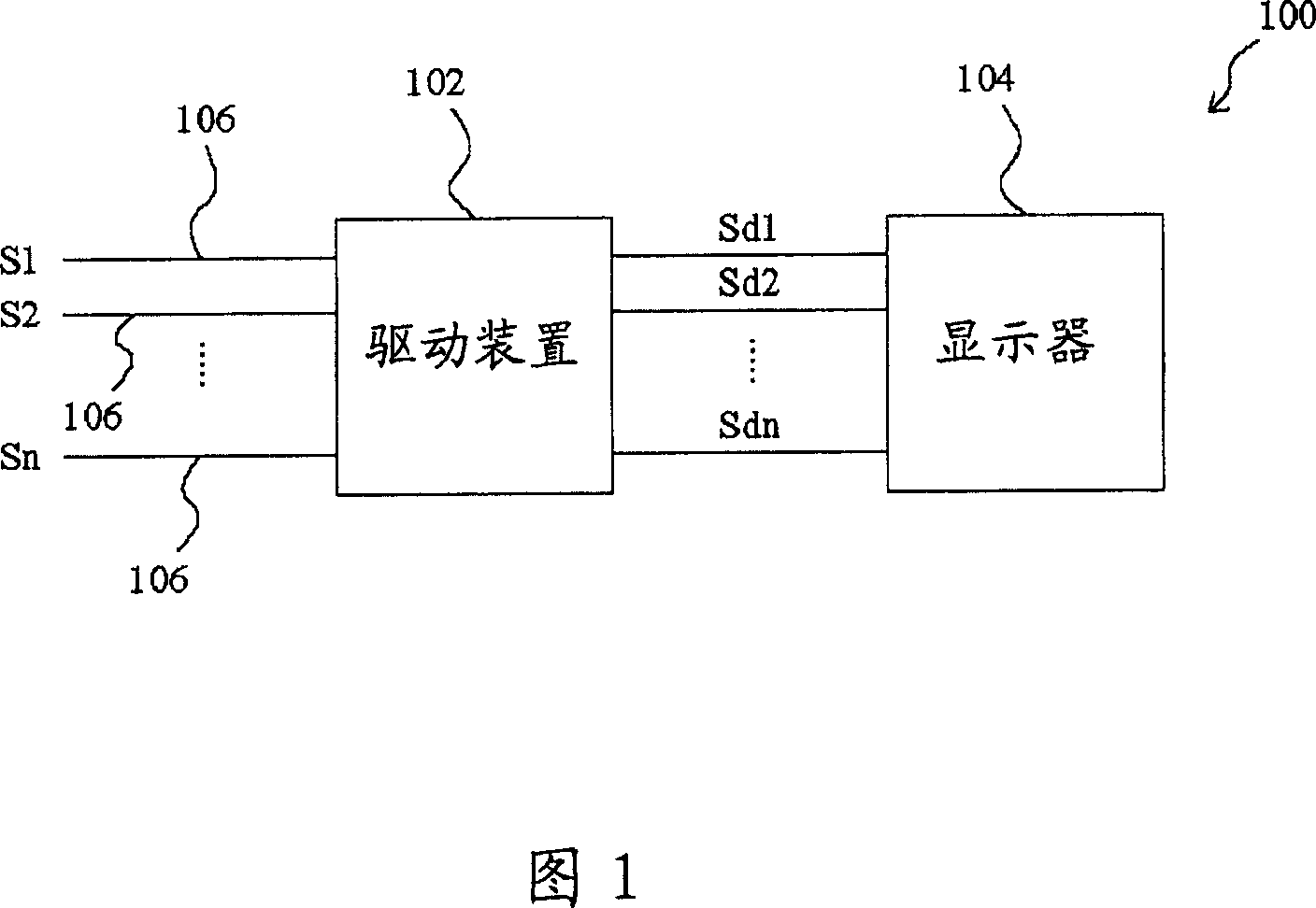
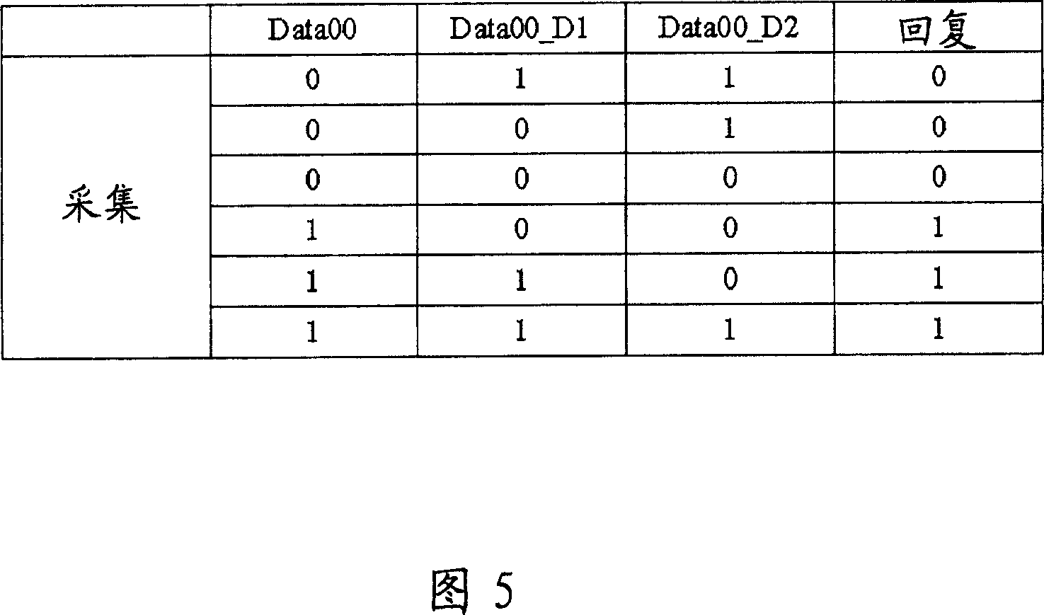
[0040] 2 is an embodiment of the drive device 200 of the present invention, wherein the registers 208, 210 to 212 receive and store the pulse signal CLKN, the data signal D00N to D22N and the signal P from the input terminals 202, 204 to 206 respectively. After the buffers 208, 210 to 212, they are output together to the receivers 214, 216 to 218, to eliminate the delay caused by the internal running lines 2022, 2024, 2042, 2044, 2062 and 2064, the receivers 214, 216 to 218 to output the signal Sc and the data signals Data00 to Data22 to the pulse generator 220 and the multiple data acquisition circuits 222 to 224 respectively according to the received data, and the pulse generator 220 generates a pulse CLK according to the signal Sc to the multiple data acquisition circuits 222 to 224 , for collecting the data signals Data00 to Data22 to generate the collection signals S1, S2 and S3, and the reply circuits 226 to 228 store a table for comparison with the collection signals S1,...


PUM


Abstract

The invention relates to a driving device for display and the method. It delays data signal at least once through multiple data gathering circuit. A pulse would gather the data signal and the delayed data signal. The gathered data would be compared to preset table to output accurate original data.

Description


Claims


Application Information

Patent Timeline
Owner ELAN MICROELECTRONICS CORPORATION
Why Eureka
Try Eureka