Heat exchangers

一种热交换器、换热管的技术,应用在热交换设备、间接换热器、换热器类型等方向,能够解决加剧、换热管温度分布不均匀、蒸发器难以具有热交换性能等问题,达到热交换效率提高、空气温度均匀的效果

Inactive Publication Date: 2007-04-18
KEIHIN THERMAL TECH CORP
View PDF5 Cites 10 Cited by
  • Summary
  • Abstract
  • Description
  • Claims
  • Application Information

AI Technical Summary

Problems solved by technology

Therefore, the temperature distribution of the heat exchange tubes in the rear tube group is uneven, and the unevenness will become more noticeable
Therefore, the air flowing through the heat exchange core of the evaporator has varying temperatures in some parts of the heat exchange core, and it is difficult for the evaporator to have sufficiently improved heat exchange performance
This problem is exacerbated especially when the refrigerant flow rate varies or if the air flow through the heat exchange core varies at some positions

Method used


Image

  • Heat exchangers
  • Heat exchangers
  • Heat exchangers

Examples


Embodiment Construction

[0065] Embodiments of the present invention will be described below with reference to the drawings.

[0066] In the following description, upper and lower parts and left-hand and right-hand sides of FIGS. 1 and 2 will be referred to as "upper", "lower", "left" and "right", respectively.

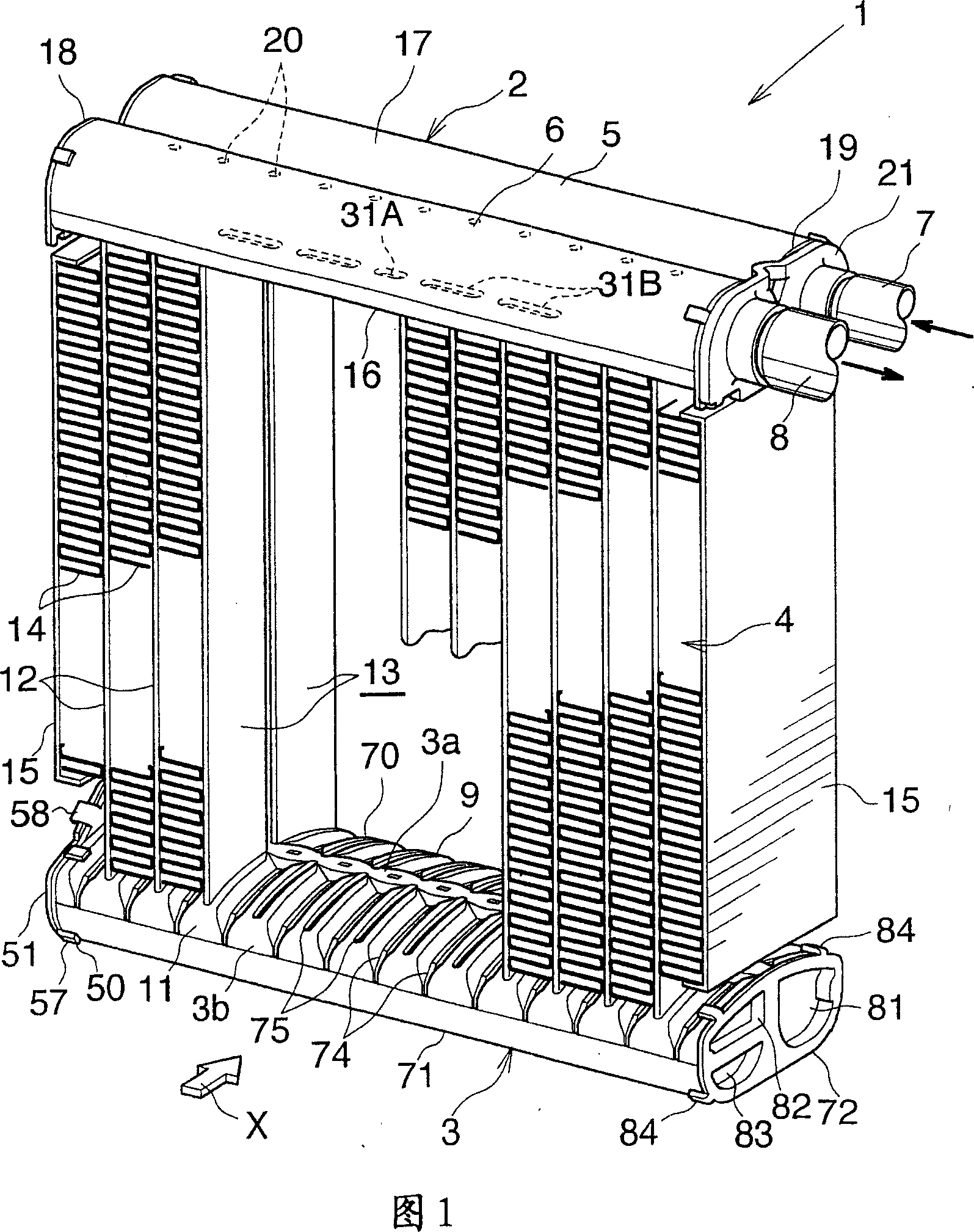
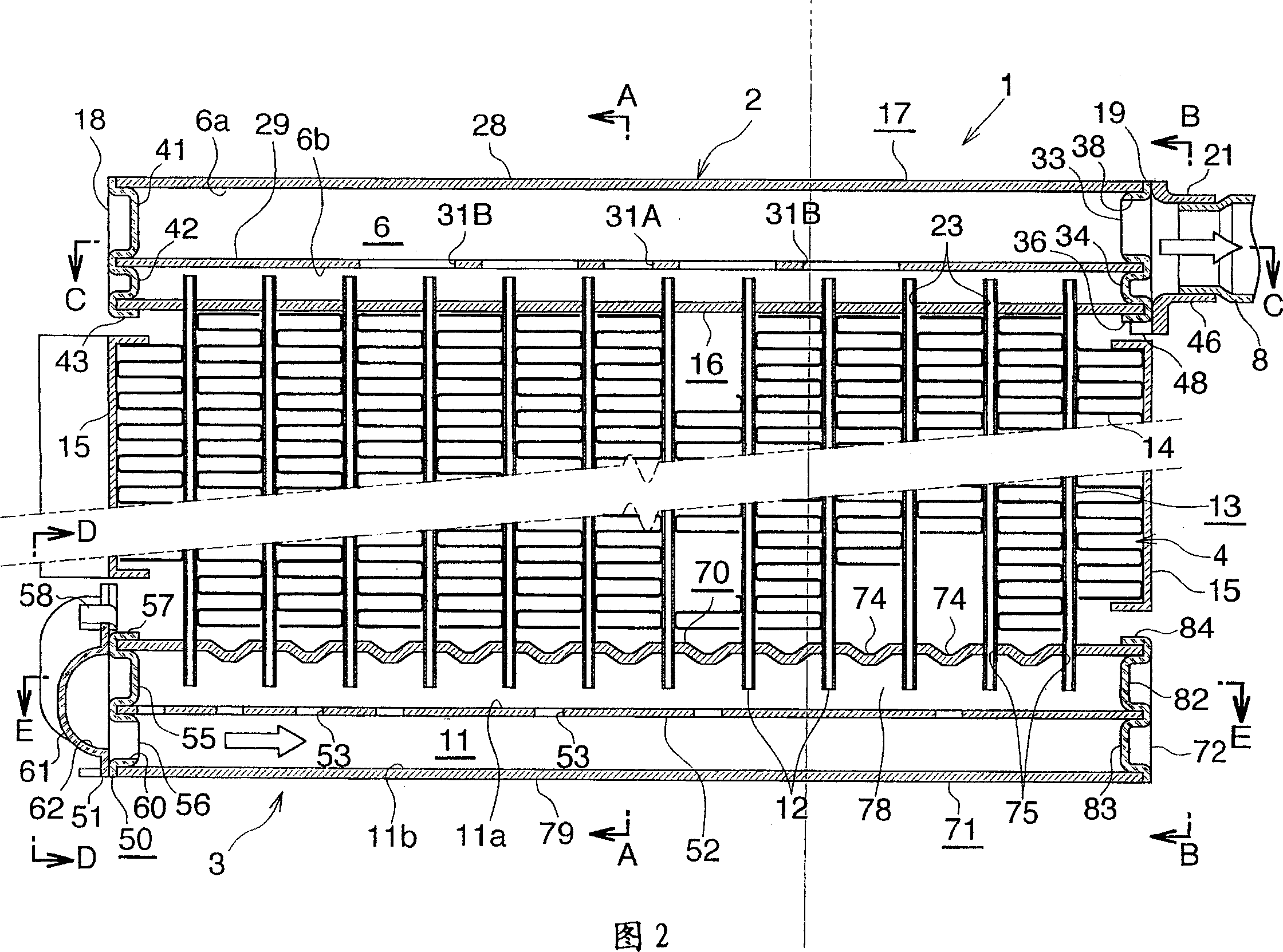
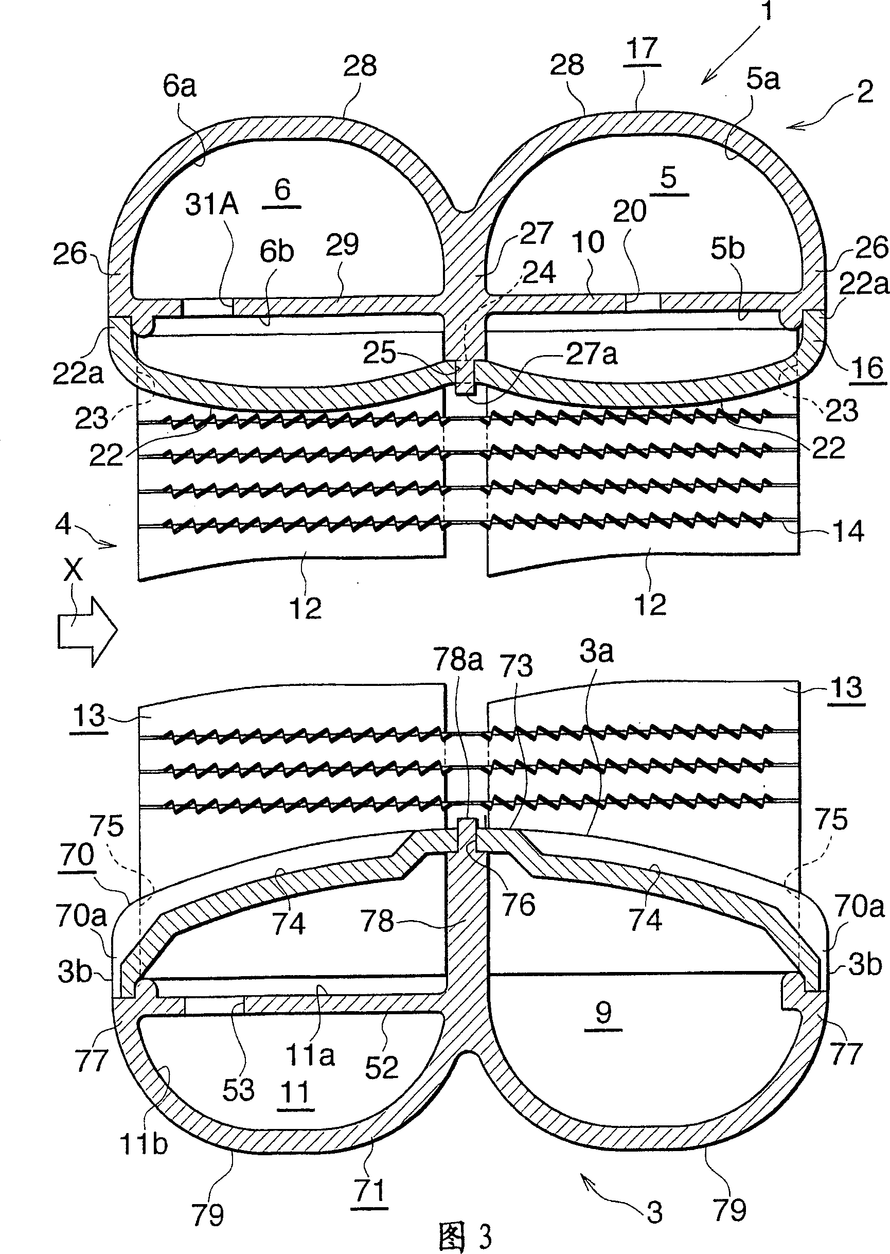
[0067] 1 and 2 show the overall structure of an evaporator to which the heat exchanger of the present invention is applied, FIGS. 3 to 10 show the structure of a main part, and FIG. 11 shows how refrigerant flows through the evaporator.

[0068] Figures 1 and 2 show an evaporator 1 comprising an aluminum refrigerant inlet-outlet box 2 and an aluminum refrigerant diversion box 3 arranged up and down at intervals, and an aluminum refrigerant diversion box 3 arranged between the two boxes 2, 3 The heat exchange core 4.

[0069] The refrigerant inlet-outlet box 2 includes a refrigerant inlet header 5 arranged at the front (downstream side with respect to the direction of air flow through the eva...


PUM


Abstract

An evaporator 1 comprises a heat exchange core 4 having heat exchange tubes 12 in groups 13, a refrigerant inlet header 5 and a refrigerant outlet header 6 which are arranged toward one end of each of the heat exchange tubes 12, and a refrigerant inflow header 9 and a refrigerant outflow header 11 which are arranged toward the other end of each heat exchange tube 12. The outflow header 11 has its interior divided by a flow dividing control wall 52 into two spaces 11a, 11b arranged one above the other. The inflow header 9 and the lower space 11b of the outflow header 11 are held in communication each at one end thereof. The control wall 52 has a plurality of refrigerant passing holes 53 arranged at a spacing longitudinally thereof.

Description

[0001] Cross References to Related Applications [0002] This application was filed pursuant to 35 U.S.C. §111(a) and filed pursuant to 35 U.S.C. §119(e)(1) on May 14, 2004 and December 21, 2004, respectively, under 35 U.S.C. §111(b) ) filing date benefits of provisional applications No. 60 / 570,823 and No. 60 / 637,438 filed. technical field [0003] The present invention relates to heat exchangers, and more particularly to heat exchangers suitable for use as, for example, evaporators in automotive air-conditioning units, which are refrigeration cycles to be installed in automobiles. [0004] The term "aluminum" as used herein and in the appended claims includes aluminum alloys in addition to pure aluminum. The downstream side (the direction indicated by the arrow X in Figures 1, 3, 5, 6, 8, 9 and 11) of the air flow passing through the gap between the adjacent pairs of heat exchange tubes of the heat exchanger will be at Herein and in the appended claims it is referred to as ...

Claims


Application Information

Patent Timeline
Patent Type & Authority Applications(China)
IPC IPC(8): F28F9/22B60H1/32F25B39/02F28D1/053F28F9/02F28F9/04F28F27/02
CPCF25B39/022F25D2500/02F28D1/05391F28F9/0224F28F9/0246F28F9/0253F28F9/0278
Inventor 东山直久
Owner KEIHIN THERMAL TECH CORP
Why Eureka
Try Eureka