Predicted method of radiation field strength mode of short wave antenna

A short-wave antenna and model prediction technology, which is applied in the antenna radiation pattern, electromagnetic field characteristics, etc., can solve the health and safety threats of testers, consume a lot of manpower, time and cost, troubles and other problems

Active Publication Date: 2007-04-25
CHINA SHIP DEV & DESIGN CENT
View PDF0 Cites 25 Cited by
  • Summary
  • Abstract
  • Description
  • Claims
  • Application Information

AI Technical Summary

Problems solved by technology

Due to the complex structure and boundary conditions of complex platforms such as ships and aircraft, when using electromagnetic calculation software to calculate, due to the limitation of the accuracy of the calculation method and calculation model and the capacity of the computer, the calculation results have a large error with the actual situation
On the one hand, it is difficult to completely simulate the actual structural environment of the complex platform after the antenna is installed, and the radiation field distribution generated by the short-wave transmitting antenna is greatly affected by the structural environment. Due to the differences in boundary conditions such as the structural environment, the measurement results still cannot accurately reflect the distribution of electromagnetic field strength generated by the shortwave antenna installed on the actual platform; A threat to the health and safety of testers
After the platform is built, the actual measurement will be carried out. If the measured short-wave radiation field strength exceeds the standard in key parts, it will be necessary to modify the built platform, which will be very troublesome and require a lot of manpower, time and cost.

Method used


Image

  • Predicted method of radiation field strength mode of short wave antenna
  • Predicted method of radiation field strength mode of short wave antenna
  • Predicted method of radiation field strength mode of short wave antenna

Examples


Embodiment Construction

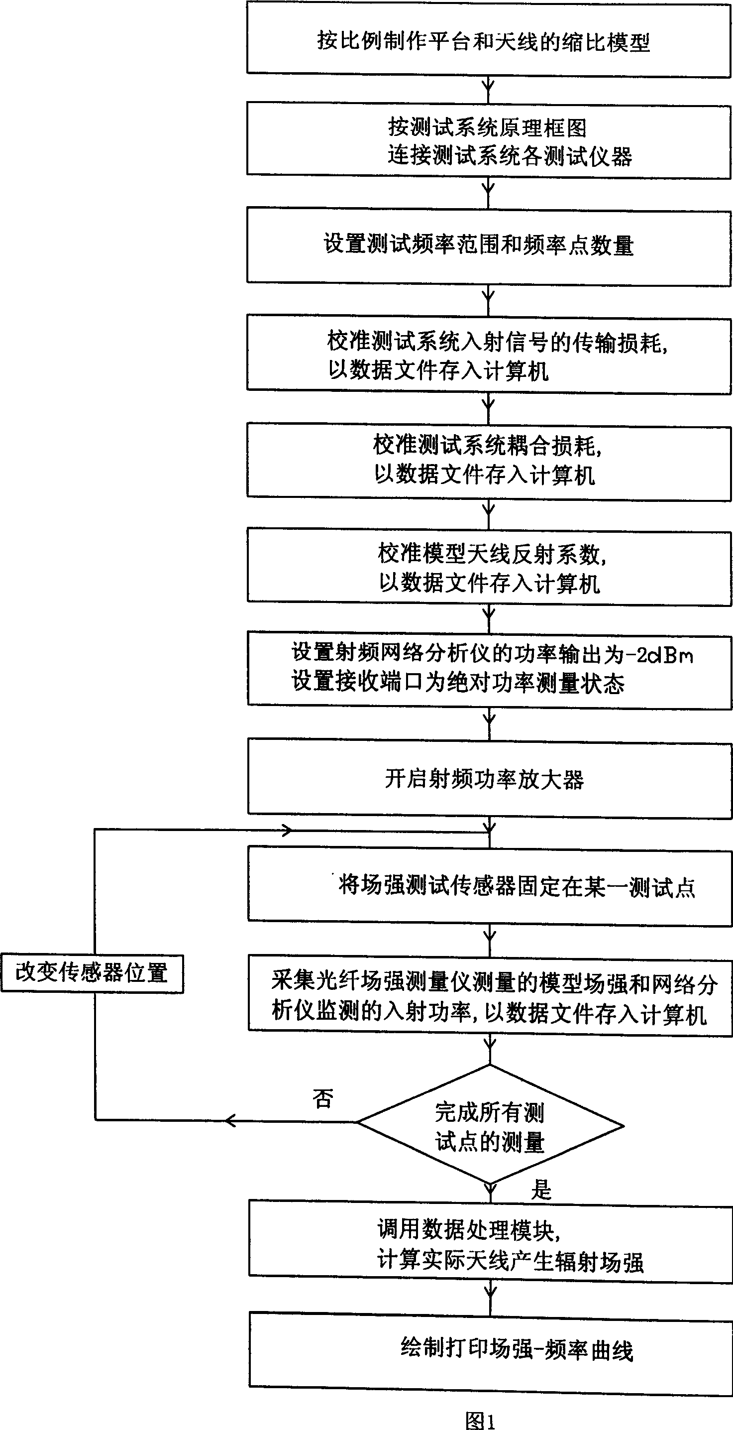
[0071] The present invention will be further described below with reference to the accompanying drawings and embodiments.

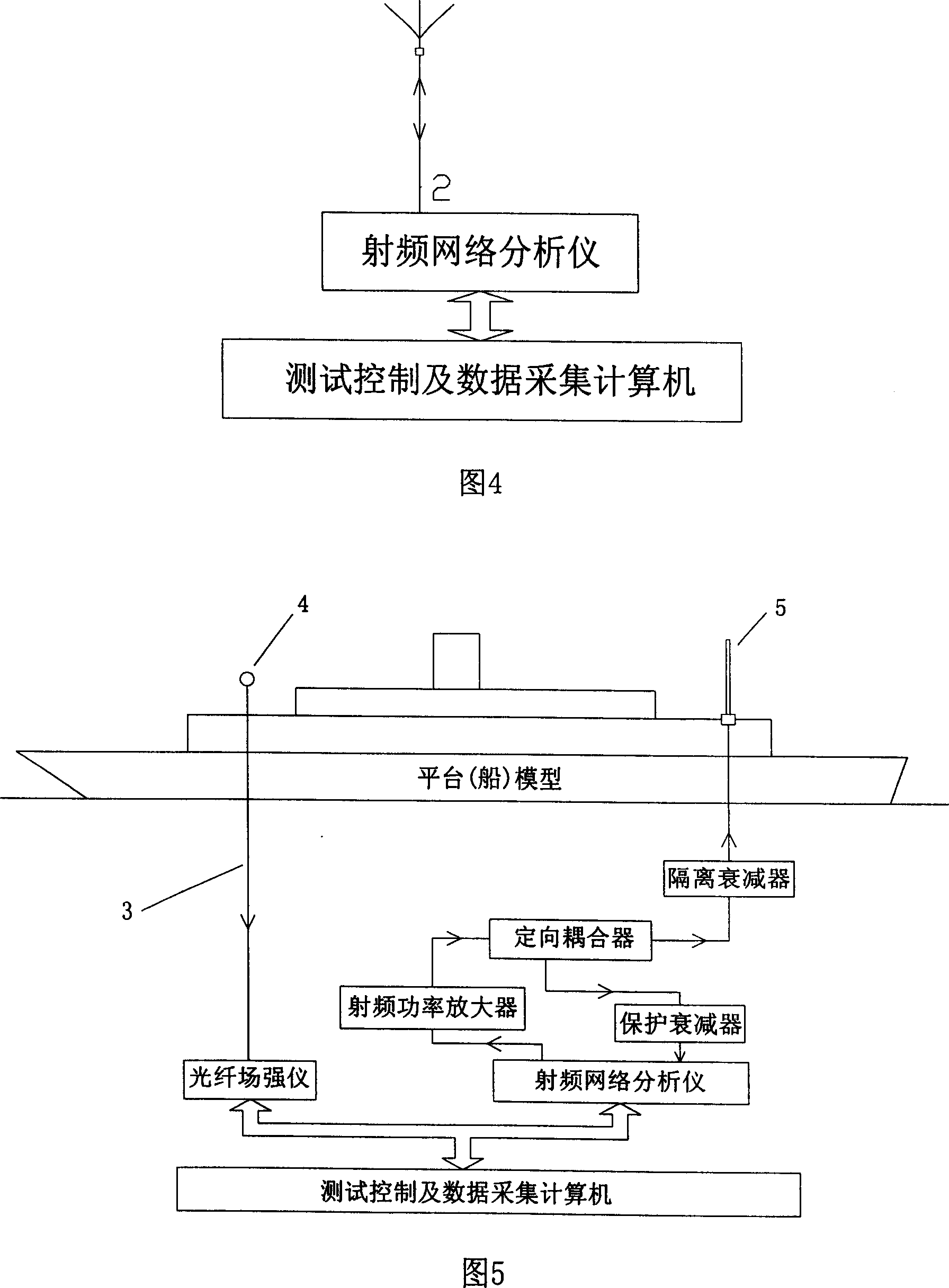
[0072] 1) First, according to the working frequency of the actual antenna and the working frequency range of the test instrument, determine the model scaling factor of 20, and use good conductors such as copper or galvanized iron to make the scaled model of the complex platform and antenna. When making a complex platform model, the metal shape and the superstructure shell that have a great influence on the antenna radiation are mainly considered. The interior of the platform can be simplified according to the needs of the model structure; the model antenna focuses on simulating the radiator and feeding part of the antenna. And install it in the corresponding position of the platform model.

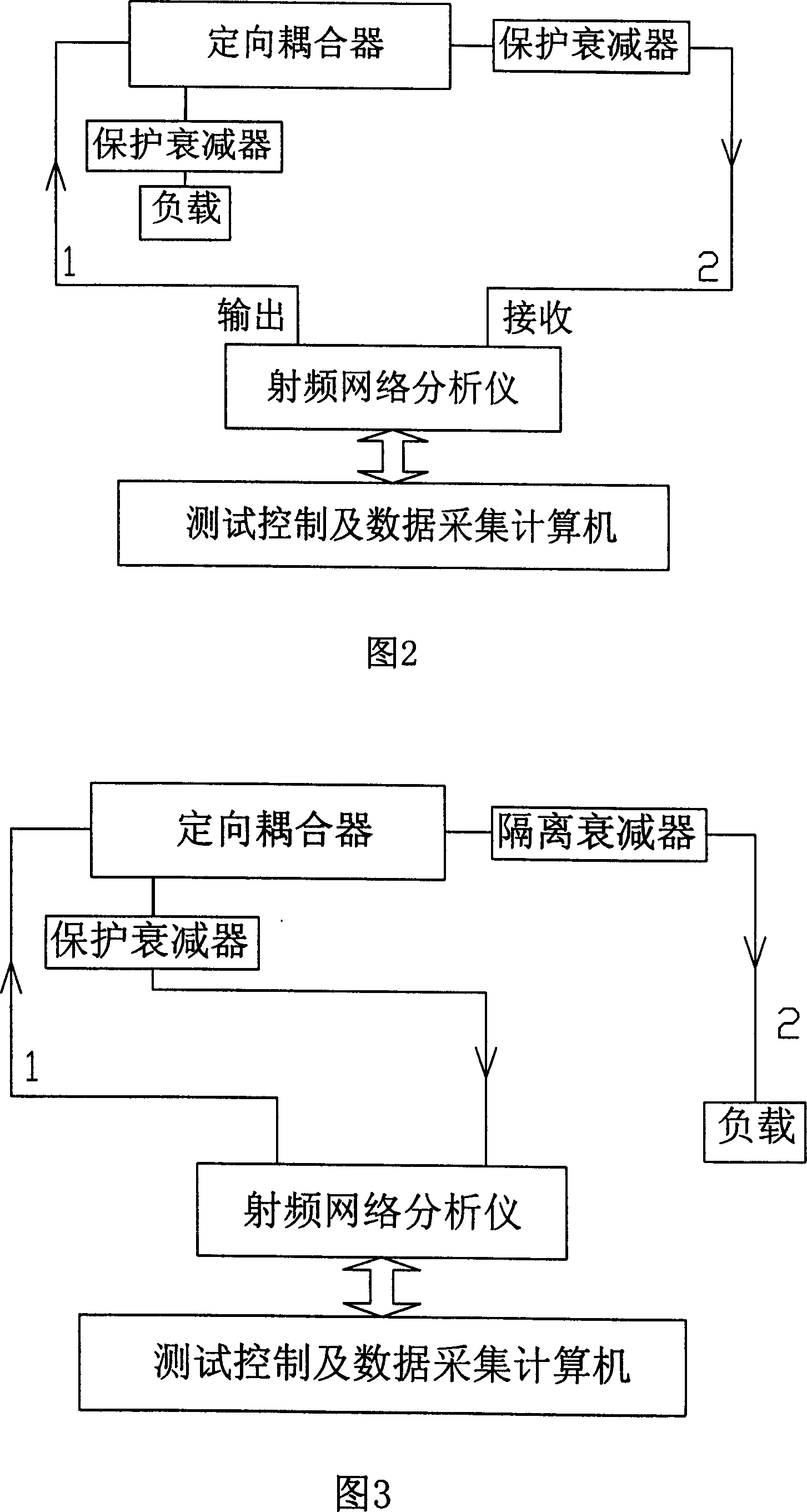
[0073] 2) Set up a short-wave antenna radiation field strength model prediction test system, including three parts: a radio frequency power transmitting unit, a field...


PUM


Abstract

The invention relates to a model prediction method of radiation intensity that is generated by the high power short-wave launching aerial mounted on the complex platform. The method is a proportion iconic model of 1:n according to the real contracture of the short wave antenna and the complex platform; The model prediction measurement system of the short-wave launching aerial radiation intensity is set; the short wave antenna of the iconic model is connected with the model prediction measurement system of the short-wave launching aerial radiation intensity; the signal output from the radiofrequency signal source of the measurement system is fed to the short wave antenna of the iconic model via the radio-frequency power amplifier, the model field intensity measured by the field intensity indicator is acquired, the data processing module software of the testing control computer calls the calibration data and the model field intensity data to calculate the radiation intensity of the real aerial. On the condition of low transmitting power in lab, the radiation intensity that is generated by the high power short-wave launching aerial mounted on the complex platform could be predicted precisely by the calibration of measurement system and the processing of module aerial radiation intensity data.

Description

technical field [0001] The invention relates to a method for model prediction of the radiation field intensity generated after a high-power short-wave transmitting antenna is mounted on a complex platform. Background technique [0002] The radiation field intensity distribution generated by high-power short-wave transmitting antennas working on complex platforms has always been the most concerned issue in the overall design of complex platforms, which directly affects the safety performance of personnel, electrical detonation devices, and fuel. At present, the prediction method of the radiation field strength generated by the high-power shortwave transmitting antenna mounted on the complex platform is mainly through the simulation calculation of the electromagnetic field calculation software, or the measurement of the radiation field strength generated by the actual antenna itself. Due to the complex structure and boundary conditions of complex platforms such as ships and ai...

Claims


Application Information

Patent Timeline
Patent Type & Authority Applications(China)
IPC IPC(8): G01R29/08G01R29/10
Inventor 郑生全黄松高吴楠温定娥刘义
Owner CHINA SHIP DEV & DESIGN CENT
Why Eureka
Try Eureka