

Magnetic force attractor of reliable suction, and convenient desorption
An attractor and de-suction technology, which is applied to the fastening devices of wing fans, permanent magnets, and building fastening devices. Effect
- Summary
- Abstract
- Description
- Claims
- Application Information
AI Technical Summary
Problems solved by technology
Method used
Image


Examples
Embodiment 1
[0028] As shown in Figure 1-6.
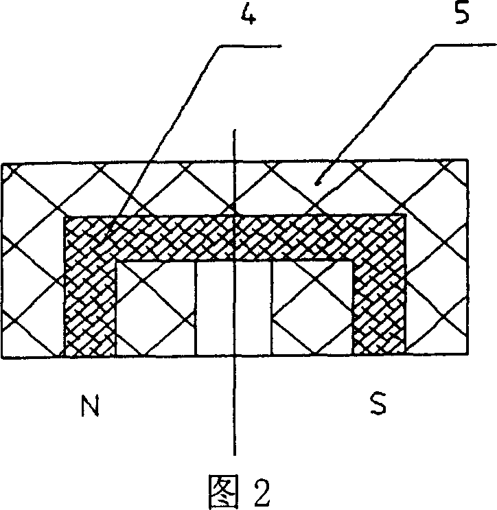
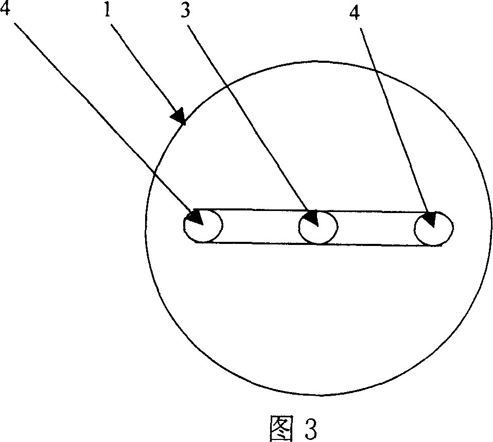
[0029] A magnetic attractor with reliable attraction and convenient desorption is composed of a base 1 equipped with a U-shaped permanent magnet 4, a sucker 2 and a rotating shaft mechanism 3 as an intermediate body equipped with a soft magnetic baton 6 and a magnetic field short-circuit bridge 7, such as Figure 1 shows. Base 1 is made up of U-shaped magnet 4 and seat body 5 (Fig. 2, 3), and U-shaped permanent magnet 4 also can be horseshoe-shaped structure or the composite structure that adds metal magnetizer to form by two permanent magnets during concrete implementation. The suction cup 2 is composed of two soft magnetic batons 6, a magnetic field short-circuit bridge 7 and a seat body 9, as shown in Figures 4, 5, and 6. The matching shaft (or axle sleeve) 10 on the base is formed, and the effect of the rotating shaft mechanism 3 is to prevent the base 1 and the suction cup 2 from departing from the magnetic force range in the process of re...
Embodiment 2
[0036] As shown in Figure 8.
[0037]A magnetic door stopper with reliable attraction and convenient desorption mainly consists of a horseshoe-shaped permanent magnet 25, two magnetic relay bars 26, a magnetic short-circuit bridge 27 and two installation blocks 28, 29 connected to the door surface, wherein the horseshoe-shaped permanent magnet 25 and The rotating shaft 22 is fixedly connected, and one end of the rotating shaft 22 passes through the mounting block 28 and links to each other with the door handle 21 that drives its rotation. The magnetic relay bar 26 and the magnetic short circuit bridge 27 are all fixedly installed on the mounting block 29. The magnetic relay bar 26 and the magnetic short circuit bridge 27 and the mounting block 29 constitute the intermediate body of the present invention, and if necessary, a positioning connecting rod 24 may be provided between the mounting blocks 28 and 29 .
[0038] The working process of this embodiment is:
[0039] When in...
Embodiment 3
[0041] As shown in Figure 9.
[0042] A magnetic door stopper with reliable attraction and convenient desorption, mainly composed of two permanent magnets 33, two magnetic relay bars 34, and a magnetic short circuit bridge 35, the two permanent magnets 33 are connected by a metal magnetic connection block 37 to form a The combined U-shaped permanent magnet is connected with a driving lever 36 on the metal magnetic connection block 37, and two magnetic relay bars 34 and magnetic short-circuit bridge 35 are all fixed on the sucker seat 31, and the magnetic relay bar 34, magnetic short-circuit bridge 35 and The sucker seat 31 constitutes the intermediate body of the present invention, the sucker seat 31 is provided with a cover plate 32, the combined U-shaped permanent magnet is located in the space formed by the sucker seat 31 and the cover plate 32, and the driving rod 36 stretches out on the cover plate 32 The guide groove 38. The two magnetic relay bars 34 and the magnetic s...
PUM
 Abstract
Description
Claims
Application Information