Disk type heat exchanger

A technology of heat exchangers and heat exchange media, applied in the direction of heat exchange equipment, heat exchanger types, heat exchanger shells, etc., can solve the problems of reduced heat exchange efficiency, poor pressure loss, inconvenience, etc., to improve heat exchange efficiency Effect

Inactive Publication Date: 2007-05-09
LG ELECTRONICS (TIANJIN) APPLIANCES CO LTD
View PDF0 Cites 1 Cited by
  • Summary
  • Abstract
  • Description
  • Claims
  • Application Information

AI Technical Summary

Problems solved by technology

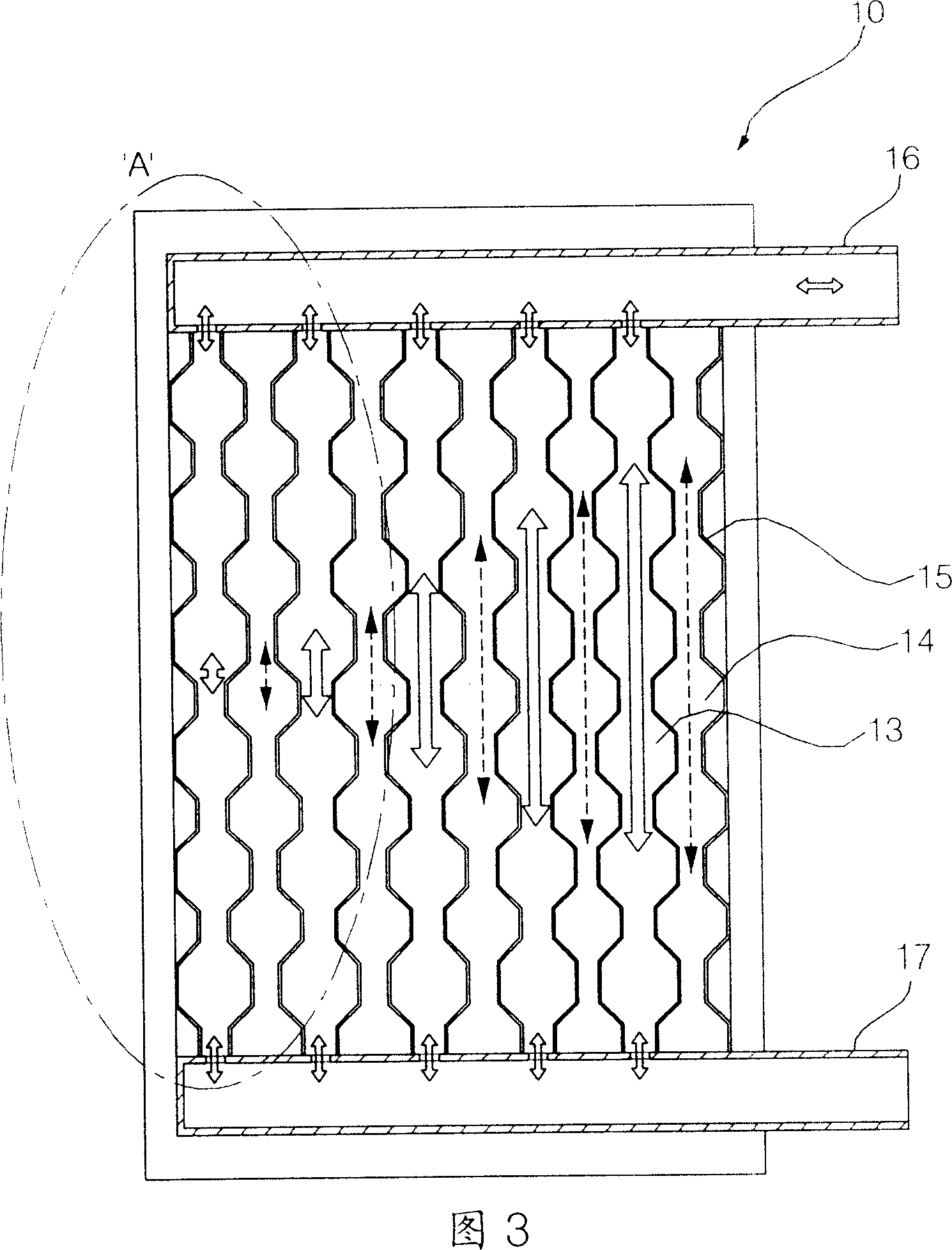
[0019] However, as mentioned above, since the plate heat exchanger 10 according to the conventional technology is a structure in which the above-mentioned plurality of first heat exchange medium passages and second heat exchange medium passages are arranged, there are the following disadvantages. The arrangement direction of the first heat exchange medium channel and the second heat exchange medium channel produces a difference in pressure loss between the first and second heat exchange medium, which makes the distribution of the first and second heat exchange medium unbalanced, so as shown in 'A of Figure 4 ’ section shows that the heat excha...

Method used


Image

  • Disk type heat exchanger
  • Disk type heat exchanger
  • Disk type heat exchanger

Examples


Embodiment Construction

[0043]In order to further explain the technical means and effects of the present invention to achieve the intended purpose of the invention, the specific implementation, structure, characteristics and features of the plate heat exchanger proposed according to the present invention will be described below in conjunction with the accompanying drawings and preferred embodiments. Efficacy, detailed as follows.

[0044] The invention will be better understood and various objects and advantages of the invention will be more fully understood by the following detailed description of the embodiments to which the invention relates with reference to the accompanying drawings.

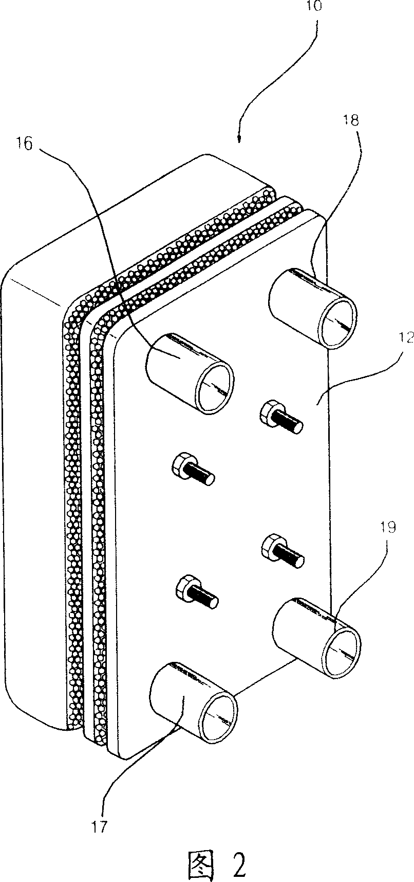
[0045] Fig. 4 is a perspective view of a disc heat exchanger according to the present invention, Fig. 5 is a structural diagram of a disc heat exchanger according to the present invention, and Fig. 6 is a heat exchange medium of a disc heat exchanger according to the present invention Oblique view of the distribut...


PUM


Abstract

A heat exchanger of tray type consists of multiple heat exchange box formed by arranging the first and the second heat exchange media channels alternatively, the first and the second heads set on said box and used for supplying or recovering the first heat exchange media, the third and the fourth heads set on said box and used for supplying or recovering the second heat exchange media, heat exchange media equally distributing unit for distributing two said medias equally in two said channels.

Description

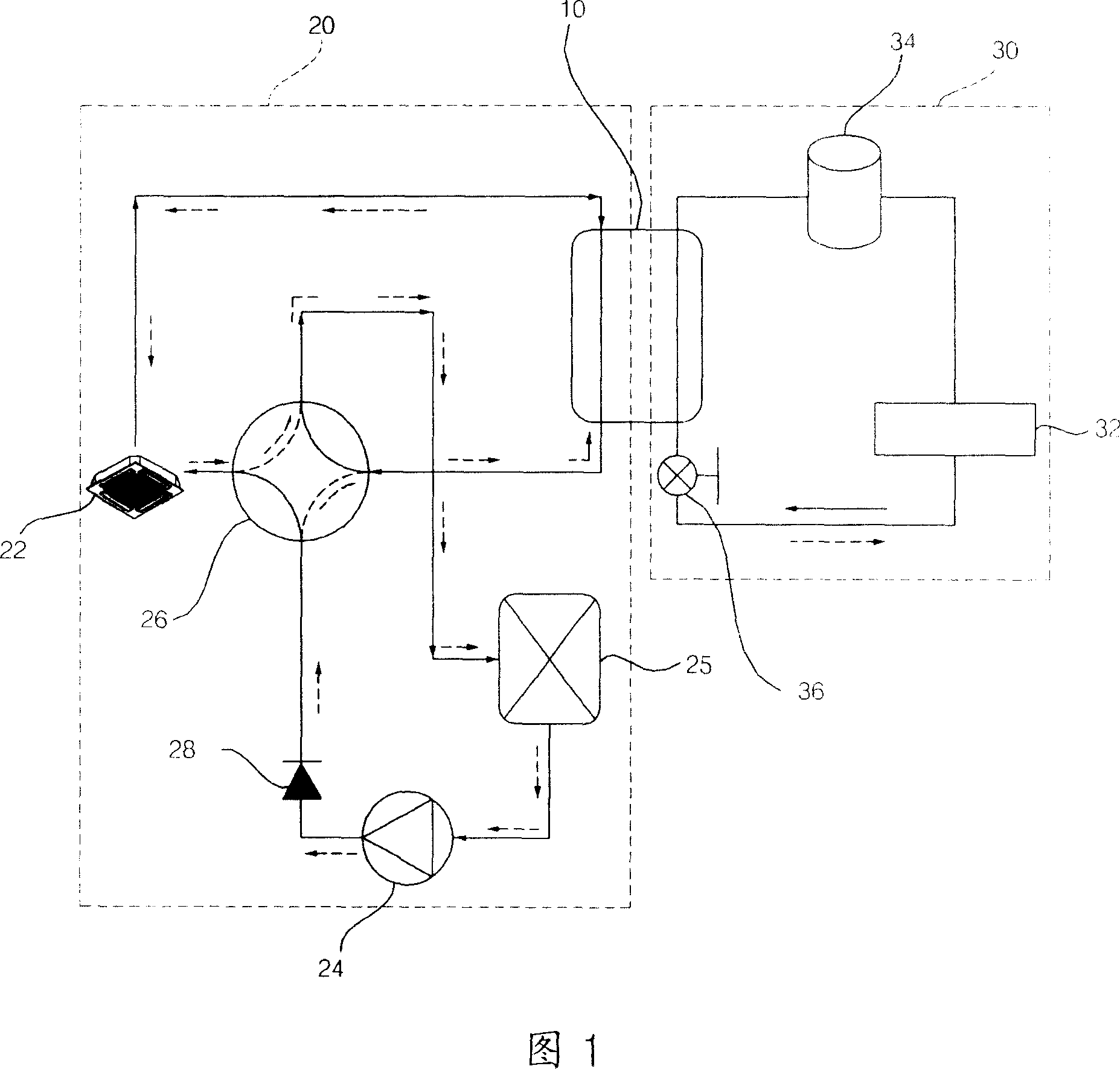
technical field [0001] The invention relates to a disc heat exchanger in which two heat exchanging media exchange heat with each other, in particular to a disc heat exchanger which can evenly distribute the heat exchanging media. Background technique [0002] A common plate heat exchanger is a device in which a first heat exchange medium and a second heat exchange medium exchange heat with each other. As such, plate heat exchangers are widely used in large-capacity air-conditioning systems. [0003] Please refer to Fig. 1 , which is the operating procedure diagram of a general large-capacity air-conditioning system. The large-capacity air-conditioning system shown in Figure 1 includes: a plate heat exchanger 10 for mutual heat exchange between the first heat exchange medium and the second heat exchange medium; it is connected with the above-mentioned plate heat exchanger 10 to form the above-mentioned first heat exchange medium air conditioner The first air-conditioning pa...

Claims


Application Information

Patent Timeline
IPC IPC(8): F28D9/02F28F9/22
Inventor 金柱沅
Owner LG ELECTRONICS (TIANJIN) APPLIANCES CO LTD
Why Eureka
Try Eureka