Light guidance plate

A light guide plate and light incident surface technology, applied in the field of light guide plates, can solve the problems of uneven light, easy to generate light beams, halos and dark bands, and uneven light output brightness of the light guide plate, so as to achieve the best light splitting effect and improve uniformity Effect

Inactive Publication Date: 2007-05-09
HONG FU JIN PRECISION IND (SHENZHEN) CO LTD +1
View PDF0 Cites 4 Cited by
  • Summary
  • Abstract
  • Description
  • Claims
  • Application Information

AI Technical Summary

Problems solved by technology

[0003] A light guide plate in the prior art includes a light incident surface, a light exit surface connected to the light incident surface and a bottom surface opposite to the light exit surface, the light incident surface is provided with microstructures perpendicular to the light exit surface, the The microstructure is usually a V-shaped groove. The light emitted by the li...

Method used


Image

  • Light guidance plate
  • Light guidance plate
  • Light guidance plate

Examples


Embodiment Construction

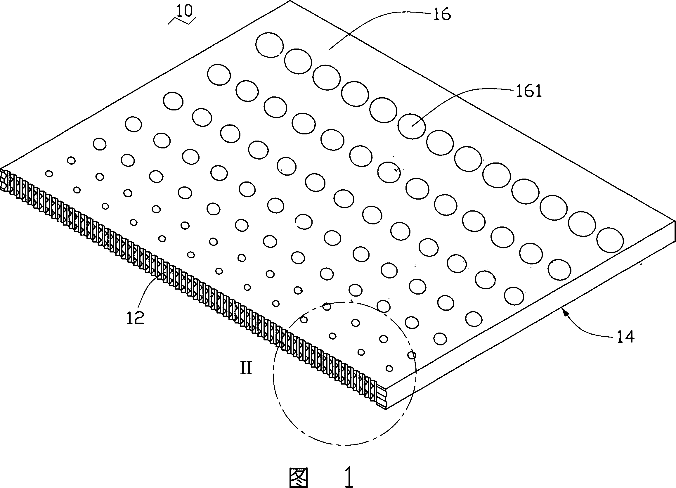
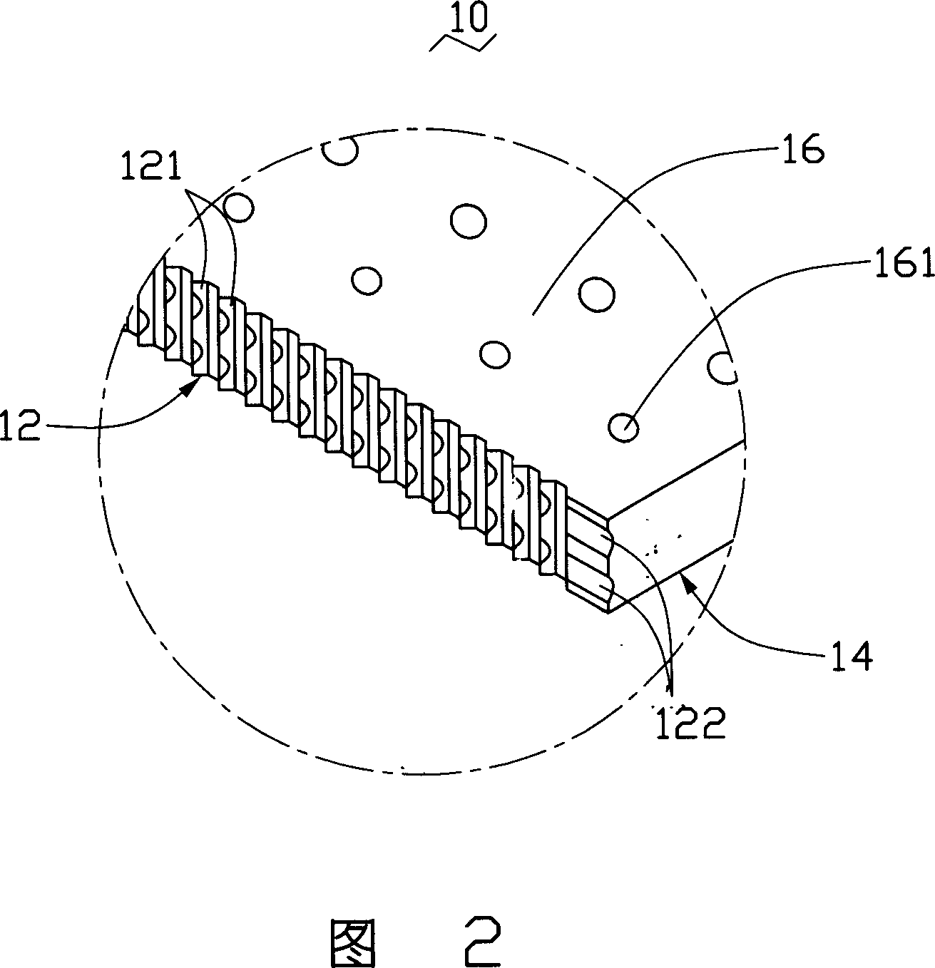
[0011] Please refer to Fig. 1 and Fig. 2, which are the light guide plate 10 provided by the first embodiment of the present invention, the light guide plate 10 includes a light incident surface 12, a light exit surface 14 connected to the light incident surface 12 and a Bottom 16.

[0012] The light guide plate 10 is flat. External light enters the light guide plate 10 through the light incident surface 12 , is reflected by the bottom surface 16 , and passes through the light exit surface 14 .

[0013] The light incident surface 12 is provided with a plurality of first groove-shaped microstructures 121 and a plurality of second groove-shaped microstructures 122, wherein the extension direction of the first groove-shaped microstructures 121 is perpendicular to the light-emitting surface 14, and the second groove-shaped microstructures The extension direction of the microstructure 122 is parallel to the light-emitting surface 14, that is, the first groove-shaped microstructure ...


PUM


Abstract

A light guide plate consists of a light incoming surface, a light outgoing surface connected with light incoming surface and bottom surface being set in opposite to light outgoing surface. It is featured as arranging the first groove shaped microstructure the second groove shaped microstructure on light incoming surface and crossing two said microstructures with each other.

Description

【Technical field】 [0001] The invention relates to a light guide plate. 【Background technique】 [0002] Liquid crystal display devices have the advantages of lightness, thinness, and low power consumption, and are widely used in modern information equipment. Since the liquid crystal panel itself in the liquid crystal display device does not have luminous characteristics, in order to achieve the display effect, it is necessary to provide a surface light source device for the liquid crystal panel, such as a backlight module. The function of the surface light source device is to provide the liquid crystal panel with sufficient and uniform surface light source . The light guide plate is a key component in the surface light source device, and it must have a good optical design so that the light guide plate can guide the light emitted by the light source and convert it into a surface light source with a certain brightness and chromaticity. [0003] A light guide plate in the prio...

Claims


Application Information

Patent Timeline
IPC IPC(8): G02F1/1335
Inventor 张佳煌
Owner HONG FU JIN PRECISION IND (SHENZHEN) CO LTD
Why Eureka
Try Eureka