Optical modulator

A technology of optical modulator and modulation voltage, which is applied in the field of optical communication system, and can solve the problem of not teaching beam frequency chirp etc.

Inactive Publication Date: 2007-05-09
PIRELLI & C
View PDF6 Cites 11 Cited by
  • Summary
  • Abstract
  • Description
  • Claims
  • Application Information

AI Technical Summary

Problems solved by technology

Furthermore, the document does not teach how the frequency chirp of the modulated beam can be controlled

Method used


Image

  • Optical modulator
  • Optical modulator
  • Optical modulator

Examples


Embodiment Construction

[0127] Figure 7 shows an embodiment of an optical modulator 1 according to the present invention, the optical modulator 1 comprising: a Mach-Zehnder structure, a first electrode structure 20, a second electrode structure 21, a third electrode structure 22, an optional A fourth electrode structure 23, and drive circuitry for driving the first, second, third, and fourth (if present) electrode structures 20, 21, 22, 23.

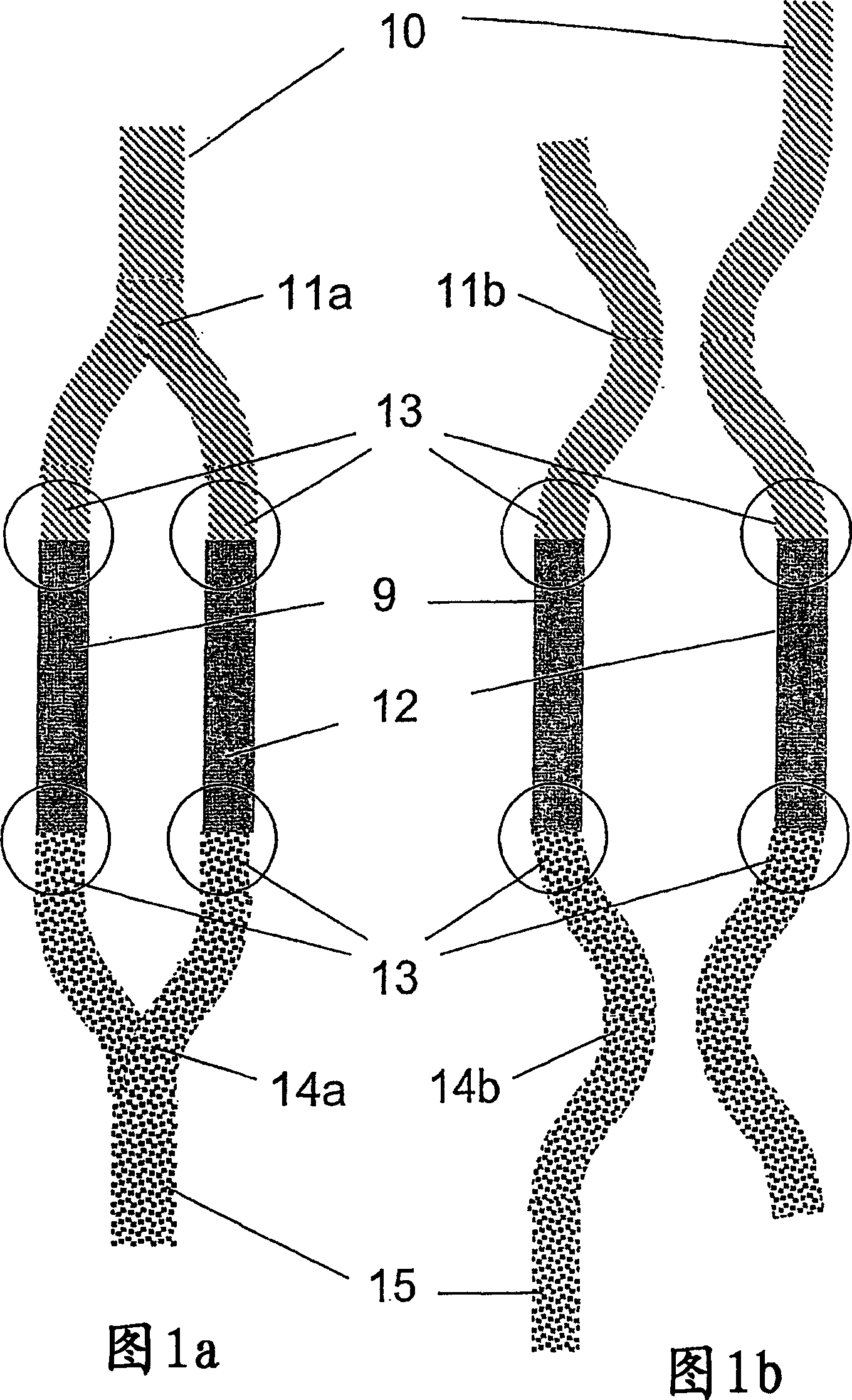
[0128] In the embodiment of FIG. 7 (see also FIG. 1a), the Mach-Zehnder structure includes an input waveguide 10; a beam splitter 11a that splits the input beam into two beams; Second waveguide arms 9 and 12; combiner 14a combining the two beams into an output beam; output waveguide 15; junction area 13 between waveguide arms 9, 12 and beam splitter 11a and optical combiner 14a.

[0129] In the optical modulator 1, the first electrode structure 20 is combined with the first waveguide arm 9, the second electrode structure 21 is combined with the second waveguide ...


PUM


Abstract

An optical modulator comprising an optical splitter for splitting an input light beam into a first and second light beam; a first and a second waveguide arm connected to said optical splitter for receiving and transmitting therethrough said first and second light beam, respectively, said waveguide arms each including a core region comprising a group IV semiconductor material or a combination of group IV semiconductor materials; an optical combiner connected to said f irst and second waveguide arm for receiving said first and second light beam and combine them into an output light beam, a first and a second electrode structure associated with said first and second waveguide arm , respectively; a driving circuit for supplying voltage to said first and second electrode structure , characterized in that said driving circuit is adapted to supply a first modulation voltage superimposed to a first bias voltage to the first electrode structure and a second modulation voltage superimposed to a second bias voltage to the second electrode structure.

Description

technical field [0001] The invention relates to a light modulator and a method of modulating the intensity of a light beam. [0002] The invention also relates to a unit comprising the optical modulator, a transmitting station, and an optical communication system. Background technique [0003] In digital communication systems, information in the form of digital electrical signals is encoded onto an optical carrier wave, as described by I.P. Kaminow and T.L. , the approach adopted earlier is to directly modulate the laser. In a typical configuration for direct modulation, an electrical signal is combined with a bias current applied to the laser terminals. However, when modulation is attempted at data bit rates exceeding about 1-2 Gb / s, an undesirable optical frequency change known as chirping occurs. These frequency changes shift the frequency of the excited laser light, broadening the optical spectrum of the transmitted pulse. As the sign and magnitude of the usual laser...

Claims


Application Information

Patent Timeline
Patent Type & Authority Applications(China)
IPC IPC(8): G02F1/225G02F1/17G02F1/01G02F1/21
CPCG02F1/2257G02F1/0123G02F2001/212G02F1/212
Inventor 塞尔维亚·基蒂尼安东尼奥·尼斯伯拉
Owner PIRELLI & C
Why Eureka
Try Eureka