Joint source-channel decoding method and associated joint source-channel decoder

A technology of joint decoding and channel decoding, applied in the field of source-channel joint decoder, can solve the problems of high complexity, not using prior knowledge, etc., and achieve the effect of low complexity

Inactive Publication Date: 2007-05-09
FRANCE TELECOM SA
View PDF1 Cites 9 Cited by
  • Summary
  • Abstract
  • Description
  • Claims
  • Application Information

AI Technical Summary

Problems solved by technology

[0018] The main disadvantage of those methods is that for flexible source decoding or source-aided channel decoding, they do not exploit a priori knowledge of the association of the source
[0028] Despite these simplifications, this method suffers from the disadvantage of extremely high complexity overhead

Method used


Image

  • Joint source-channel decoding method and associated joint source-channel decoder
  • Joint source-channel decoding method and associated joint source-channel decoder
  • Joint source-channel decoding method and associated joint source-channel decoder

Examples


Embodiment Construction

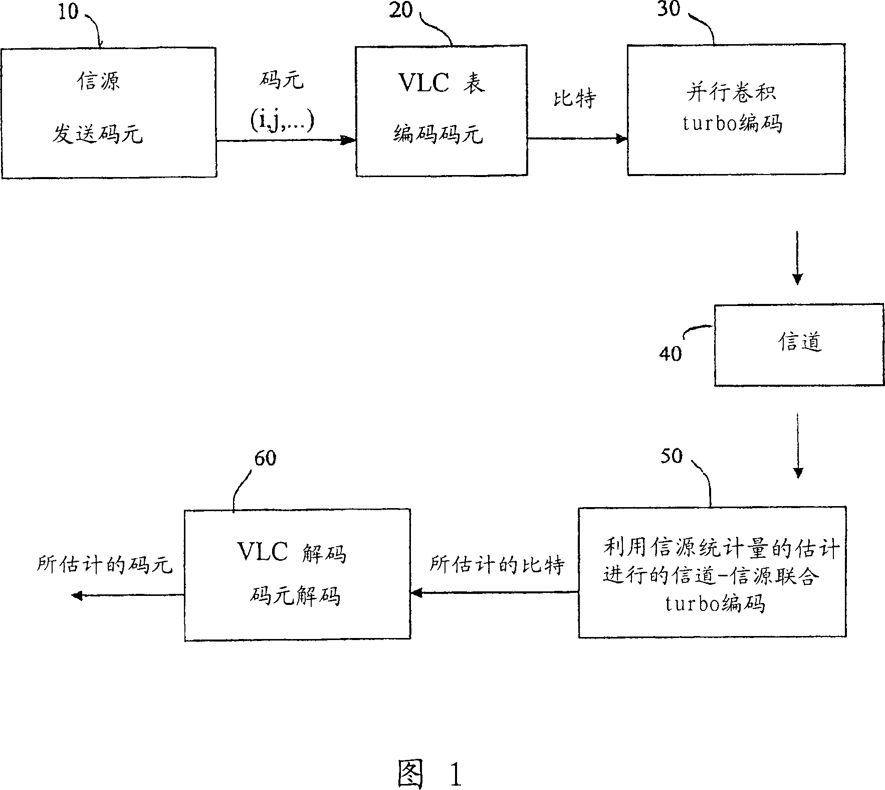
[0051] Figure 1 is a diagram representing the transmission of digital data over a transmission channel 40 from a transmitter comprising elements 10,20,30 to a receiver or decoder stage comprising elements 50,60.

[0052] The transmitter includes symbols i , j etc., the symbols may be generated independently, in which case the source is considered to be a source without memory, or may be generated in a correlated manner, e.g. A first-order Markov model of the relationship to generate the symbols. In a video encoder, these symbols i , j etc. may correspond to, for example, texture motion coefficients, quantized so as to produce a certain number of discrete values.

[0053] Said source 10 is followed by a video encoder 20 represented by a variable length code (VLC) table (for example standardized in the MPEG4 video standard). This VLC table is used in the source 10 to encode the symbols into digital data.

[0054] Finally, channel coding (eg, parallel convolutional turbo co...


PUM


Abstract

The inventive joint source-channel method for decoding digital data received by the channel decoder (51) of a digital data decoder (50), wherein said data are received by transmitting digital data coding discrete values or symbols (I, j) emitted by a source (10) through a transmission channel (40) and, wherein the probabilities associated with said symbols are applied to the channel decoding lattice of said channel decoder (51). According to said invention, said probabilities (p(i)) and (p(i/j)) are statistically evaluated by the decoder (50). The invention can be used for encoding and decoding digital data transmitted through a communications channel.

Description

technical field [0001] The invention relates to a combined source-channel decoding method. It also relates to an associated source channel joint decoder. Background technique [0002] The invention is particularly advantageously applied to the encoding and decoding of digital data transmitted over communication channels, in particular MPEG (Motion Picture Experts Group) data transmitted over UMTS mobile phone channels. [0003] Current digital communication systems providing optimized performance use individually optimized source and channel coding systems. The source coder minimizes the redundancy of the source signal to be transmitted. In contrast, channel encoders introduce controllable redundancy in order to protect information from interference inherent in any kind of transmission. [0004] Specifically, the best audio, image, and video source coding results are obtained through a discrete cosine transform (DCT) coder or a wavelet coder associated with a variable len...

Claims


Application Information

Patent Timeline
Patent Type & Authority Applications(China)
IPC IPC(8): H03M7/40H03M13/45H03M13/39H03M13/29
CPCH03M13/39H03M13/6312H03M13/2957H03M7/40H03M13/45
Inventor 马里恩·珍妮皮埃尔·西欧汉
Owner FRANCE TELECOM SA
Why Eureka
Try Eureka