
A finger-clipped saturation oxygen measuring apparatus

A measuring device and saturation technology, which is applied in diagnostic recording/measurement, medical science, sensors, etc., can solve the problems of inaccurate position, incorrect display of measurement data, unstable display, etc., and achieve the effect of accurate measurement data

Active Publication Date: 2007-05-16
BEIJING CHOICE ELECTRONICS TECH CO LTD
View PDF0 Cites 18 Cited by
  • Summary
  • Abstract
  • Description
  • Claims
  • Application Information

AI Technical Summary

Problems solved by technology

But, along with people's use, this device also exposes some shortcomings
[0005] For example: when measuring, sometimes the measured data cannot be displayed correctly; or the display is unstable
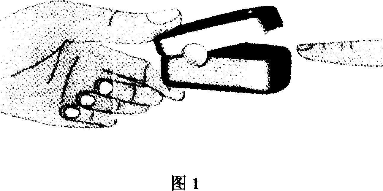
The reason is that the position where the measurer inserts his finger into the jacket is not accurate enough; or due to the difference in thickness and length of the measurer's finger, the position of the fingernail to be measured will not be aligned with the finger clip pulse oximeter. The photoelectric sensing element in the degree measuring instrument
Because the position of the measurement photocell inside the finger clip pulse oximeter is invisible from the outside, the measurer cannot align the photocell when measuring after the finger is clamped, so the above-mentioned insufficient phenomenon will occur

Method used


Image

  • A finger-clipped saturation oxygen measuring apparatus
  • A finger-clipped saturation oxygen measuring apparatus
  • A finger-clipped saturation oxygen measuring apparatus

Examples


Embodiment 1

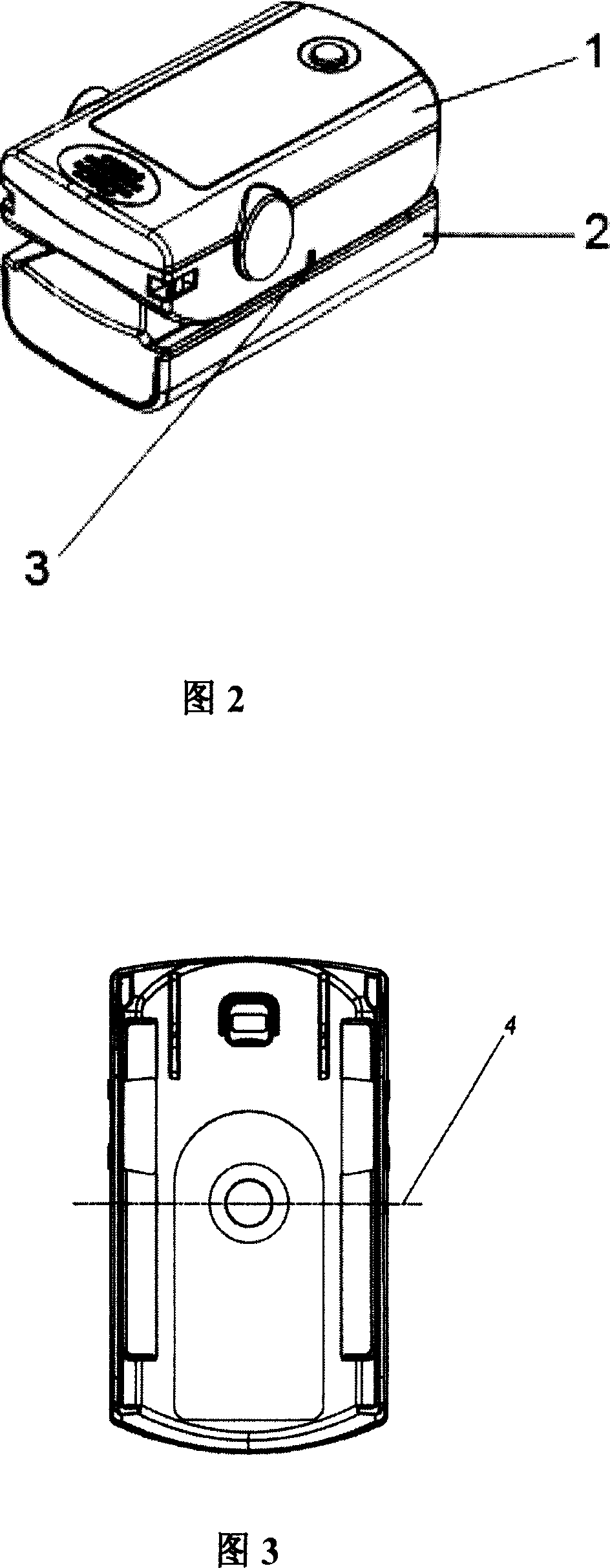
[0024] As shown in Figures 2-3, the finger-clip blood oxygen saturation measuring device of the present invention includes an upper casing 1, a lower casing 2, an elastic reset structure, a built-in detection photoelectric cell 4, and a built-in power supply and detection, processing, and control circuits, displays. A mark 3 is arranged on one side of the surface of the upper case 1; the vertical position line of the mark 3 on the side of the upper case 1 coincides with the vertical position line of the built-in detection photocell 4 arranged in the upper case 1 . The said mark 3 is protruded on the surface of the upper casing 1 . The position of the marker 3 can also be indicated by fluorescence.

[0025] Wherein, the models of the built-in detection photoelectric cell 4 are: A-OE-06, A-OE-02.

[0026] When using the present invention for measurement, the measurer puts his fingers deep between the upper case 1 and the lower case 2; Accurately measure the position of the ro...

Embodiment 2

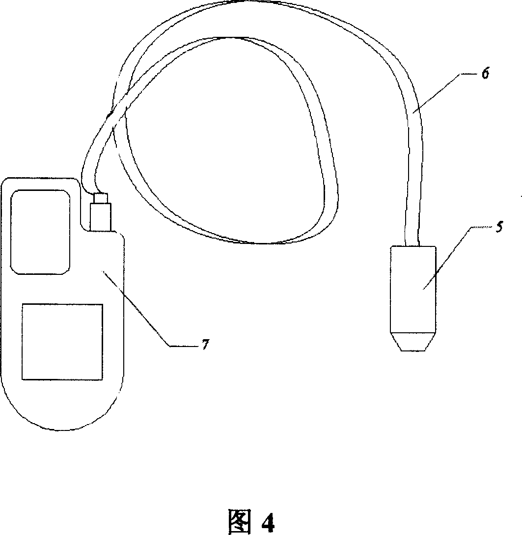
[0028] As shown in FIG. 4 , the blood oxygen saturation measuring probe device 5 of the present invention is connected to an existing hand-held oximeter or monitor 7 through a cable 6 or a connector. The main difference between the blood oxygen saturation measuring probe device 5 of the present invention and the embodiment 1 is: the built-in power supply, detection, processing, control circuit, display screen and other components are set in the hand-held oximeter or monitor 7 .

[0029] The blood oxygen saturation measuring probe device 5 of the present invention includes an upper casing 1, a lower casing 2, an elastic reset structure, and a detection photocell 4; a mark 3 is provided on one side of the surface of the upper casing 1; the mark 3 The vertical position line on the side of the upper case 1 coincides with the vertical position line of the detection photoelectric cell 4 arranged in the upper case 1 . The said mark 3 is protruded on the surface of the upper casing 1 ...


PUM


Abstract

The invention relates to a finger blood oxygen saturation tester, which comprises upper and lower frames, flexible composite structure, internal testing photoelectric tube, internal power, testing circuit, processing circuit, controlling circuit, and display, wherein the invention is characterized in that: the side of outer frame has a mark; the vertical line of said mark is superposition with the vertical line of internal testing photoelectric tube inside the frame; the mark can be protruded or concave on the side of frame, or marked with fluorescence. With said invention, the testing position can be watched simply.

Description

technical field [0001] The invention relates to a measuring device for medical treatment, in particular to a finger-clip blood oxygen saturation measuring device. Background technique [0002] Blood oxygen saturation measuring instrument is a pulse and blood oxygen saturation measuring instrument used in medical clinics to continuously monitor surgical patients or critically ill patients. During monitoring, clamp the probe of the blood oxygen saturation meter on the patient's finger; obtain clinical data of the patient's pulse and blood oxygen saturation. This kind of oximeter is mainly used in the ICU ward of the hospital, and it is often integrated with other monitoring equipment as a comprehensive monitoring instrument and set in the general ward. [0003] Nowadays, with the continuous improvement of people's living standards, people are more and more concerned about their own health status, and they need to monitor and understand their own health indicators in a timely ...

Claims


Application Information

Patent Timeline
Patent Type & Authority Applications(China)
IPC IPC(8): A61B5/1455
CPCA61B5/14552A61B5/6826A61B5/6838
Inventor 王维虎邬鹏陈磊
Owner BEIJING CHOICE ELECTRONICS TECH CO LTD
Learn More