Crane cabin

A driver's cab and crane technology, applied in the field of driver's cab, can solve problems such as unfavorable driver's health and heat energy loss, and achieve the effects of avoiding human injury, happy and convenient work, and broadening the field of vision.

Inactive Publication Date: 2007-05-16
TAIYUAN HEAVY IND
View PDF1 Cites 3 Cited by
  • Summary
  • Abstract
  • Description
  • Claims
  • Application Information

AI Technical Summary

Problems solved by technology

The cold air outlet and the hot air outlet of the air conditioner in the traditional crane cab are located on the roof of the cab, with a distance of about 500mm. The cold air directly hits the top of th...

Method used


Image

  • Crane cabin
  • Crane cabin

Examples


Embodiment Construction

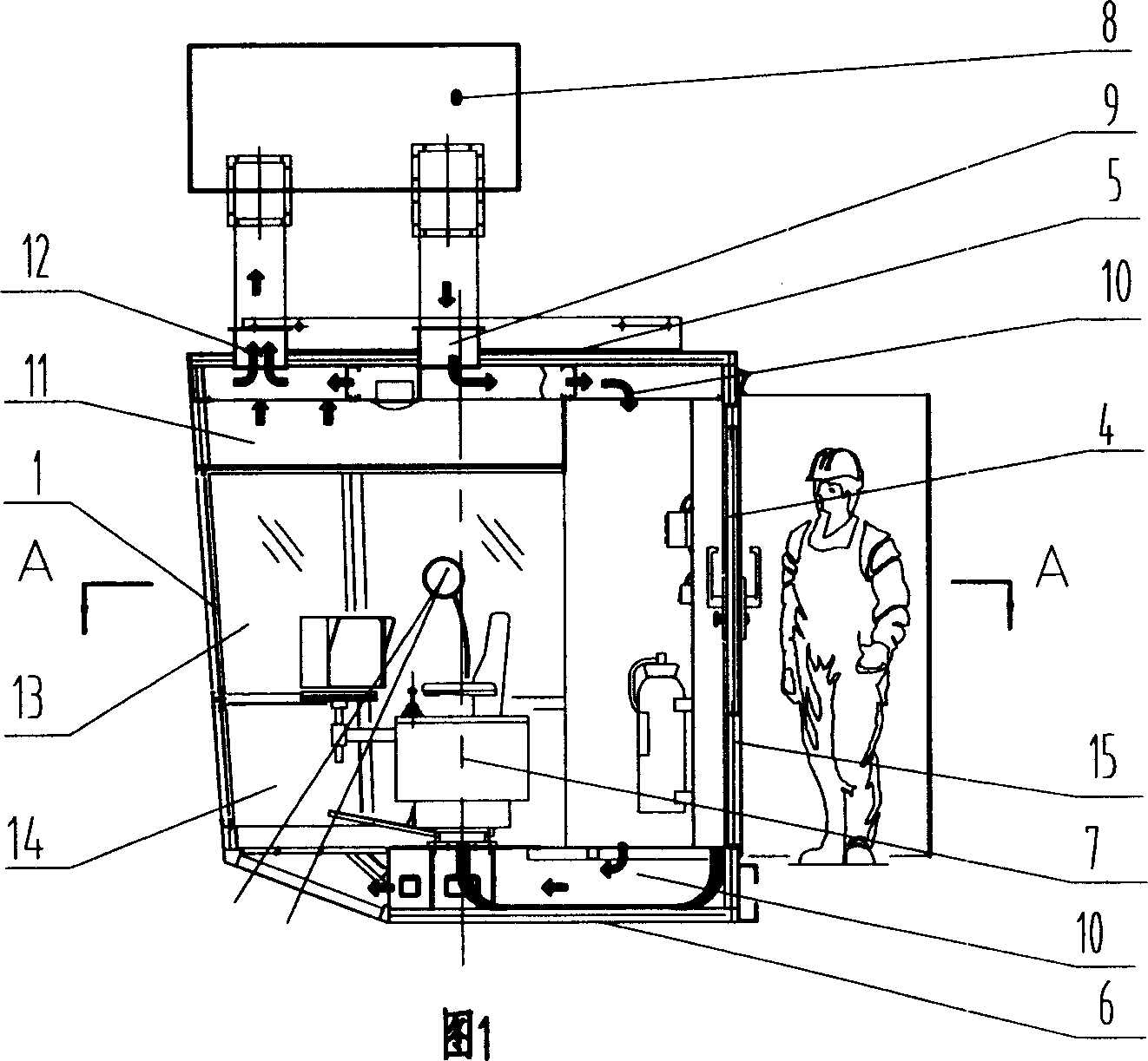
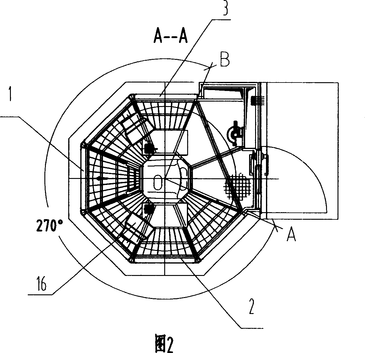
[0022] As shown in Figures 1 and 2, a crane cab is composed of a front side panel 1, a left side panel 2, a right side panel 3, a rear side panel 4, a top cover 5, and a bottom panel 6. The front window and the lower window are provided with side windows on the left and right side panels, doors are provided on the rear side panels, and a driver's seat 7 and an operating console are provided on the bottom panel in the driver's compartment. The crane driver's cab is provided with an integral air conditioner 8 above the top cover 5, and the air-conditioning cold air outlet 9 goes down to the bottom plate along the vertical wall along the top floor through the cold air duct 10, then to the seat 7 of the driver's cab, and then from the seat. The space is gradually filled from bottom to top to avoid harm to the human body. The hot air is sent from the hot air channel 11 to the air conditioner outlet 12, and the hot air is imported into the hot air channel from the ceiling in a large...


PUM


Abstract

The invention relates to a crane cab, wherein it arranges air conditioner above the top cover of cab, whose cold outlet via the cold wind channel, top layer, and upright wall, flows to the bottom plate and under the driver seat; the hot wind via the hot wind channel enters into the air condition outlet; the left and right sides of cab have upper and lower view windows; the back side plate of cab has back view window; the bottom of cab has bottom view window; the angle between the seat center and the left and right view windows is 270 degrees. The invention has wide view range.

Description

technical field [0001] The invention relates to components of a crane, in particular to a driver's cab of the crane. Background technique [0002] Crane cabs are divided into three categories. 1. Open cab. The operating platform is in an exposed environment, which is very unfavorable to people and machines (especially electrical equipment). This open structure is called a simple cab. 2. Enclosed cab. It can make the driver in a relatively independent and safe environment and reduce external interference. The non-high temperature environment adopts a single-layer wall and single-layer glass structure. 3. Special driver's cab (such as: thermal insulation driver's cab). It is suitable for workshops, warehouses, stockyards, freight yards and power stations with special requirements such as high or low temperature and harmful gas and dust hazards. [0003] Prior art such as: CN2701835Y discloses "tower crane driver's cab", is made up of front side plate, left side plate, rig...

Claims


Application Information

Patent Timeline
IPC IPC(8): B66C13/54
Inventor 胡敦忠刘李梅
Owner TAIYUAN HEAVY IND
Why Eureka
Try Eureka