Modular stacked switch cabinet

A switchgear and modularized technology, applied in pull-out switchgear, switchgear, switchgear with horizontal pull isolation, etc. The effect of assembly line operation, improving production efficiency and reducing assembly difficulty

Active Publication Date: 2014-03-26
STATE GRID CORP OF CHINA +1
View PDF6 Cites 23 Cited by
  • Summary
  • Abstract
  • Description
  • Claims
  • Application Information

AI Technical Summary

Problems solved by technology

Due to the mutual influence of the assembly of each functional unit and the limited space, it is not convenient to install at the same time, and the assembly efficiency is low
At the same time, due to the limited size of the cabinet, the space of each compartment is limited, which makes it difficult to install the components of the functional unit
Such as the installation of current transformers and grounding switches, because these two components are large and have a certain weight, and these two units are arranged in the cable room at the lower part of the cabinet. At this time, the whole cabinet has been assembled and cannot be hoisted. operation, resulting in the installation of these two components is extremely inconvenient
At the same time, the busbar room and the secondary control components are on the upper part of the cabinet, and the assemblers need to climb up to work, which poses a safety hazard
In addition, the maintenance and replacement of the internal components of the switchgear in this integrated arrangement is more complicated, especially the cabinet body, once an irreparable problem occurs, it needs to be replaced as a whole, resulting in great waste

Method used


Image

  • Modular stacked switch cabinet
  • Modular stacked switch cabinet
  • Modular stacked switch cabinet

Examples


Embodiment Construction

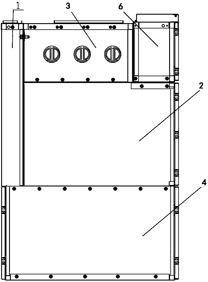
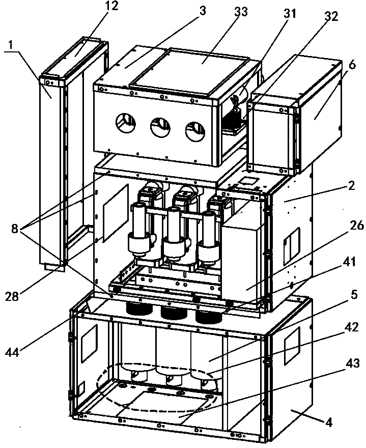
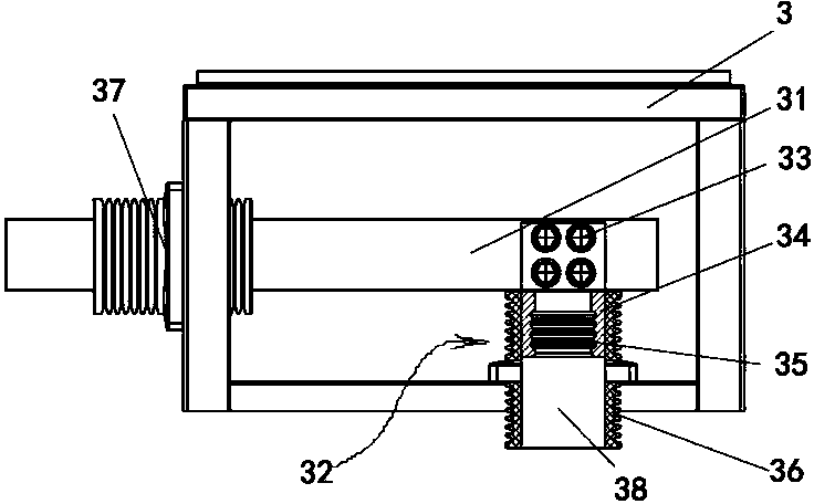
[0026] Figure 1-Figure 9 As shown, the modular stacked switchgear of the present invention includes a pressure relief chamber module 1 , a busbar chamber module 3 , an instrument box module 6 , a circuit breaker chamber module 2 , and a cable chamber module 4 . Each module includes a box structure shell and the corresponding functional devices inside the shell. The shell of each module adopts a closed sheet metal box structure, which is made of thin steel plates and assembled with bolts after bending. The sides of the shell can be Separate disassembly allows for easy installation of internal components.

[0027] The direction with larger size in the horizontal direction of the switch cabinet is the front-to-back direction, and the direction with smaller size in the horizontal direction of the switch cabinet is the left-right direction. The cable chamber module 4 is at the bottom, the pressure relief chamber module 1 and the circuit breaker chamber module 2 are placed on the ...


PUM


Abstract

The invention discloses a modular stacked switch cabinet which comprises a cable chamber module, a circuit breaker chamber module and a bus chamber module. The various modules are provided with module shells, the module shells are of case structures, the shell of the cable chamber module is adjacently connected with the shell of the circuit breaker chamber module, and the shell of the bus chamber module is adjacently connected with the shell of the circuit breaker chamber module, so that the cable chamber module, the circuit breaker chamber module and the bus chamber module are assembled with one another in a stacked manner and are detachably fixedly connected with one another; holes are formed in corresponding surfaces of each two module shells which are adjacently connected with each other, and isolation movable contacts or isolation fixed contacts can penetrate the holes so as to be connected with one another or isolated from one another. The module stacked switch cabinet has the advantages that various function units can be assembled while the various branch modules of a cabinet body are assembled, and accordingly the difficulty in assembling components inside the cabinet body can be greatly reduced.

Description

technical field [0001] The invention relates to a power transmission and distribution switchgear. Background technique [0002] At present, the switch cabinets are all arranged in an integrated way, the cabinet body is assembled, and then the internal functional units are assembled. This type of switchgear structure is such as a switchgear disclosed by CN 203260933 U. The cabinet body is separated by wall plates made of steel plates to form multiple compartments, generally including a busbar room on the rear side of the top, and a circuit breaker on the front side of the middle part. room, the cable room on the rear side of the bottom, and the circuit breaker room is equipped with a handcart circuit breaker. The handcart circuit breaker includes a handcart that moves forward and backward and is assembled on the guide rail in the horizontal direction and a circuit breaker fixed on the handcart. , the circuit breaker includes an upright arc extinguishing chamber and circuit b...

Claims


Application Information

Patent Timeline
Patent Type & Authority Applications(China)
IPC IPC(8): H02B1/30H02B11/167H02B3/00
CPCH02B11/12
Inventor 袁端磊杨芳王海燕赵芳帅朱志豪贾耿锋闫广超
Owner STATE GRID CORP OF CHINA
Why Eureka
Try Eureka