Glass substrate and a manufacturing method thereof

A technology of glass substrate and manufacturing method, applied in glass manufacturing equipment, manufacturing tools, glass molding, etc.

Active Publication Date: 2007-05-23
NIKON CORP
View PDF2 Cites 11 Cited by
  • Summary
  • Abstract
  • Description
  • Claims
  • Application Information

AI Technical Summary

Problems solved by technology

[0024] The main purpose of the present invention is to overcome the defects of existing glass substrates and provide a new type of glass substrate. The technical problem to be solved is to reduce the defect rate and manufacture FPDs with high efficiency, so that it is more suitable for practical use.

Method used

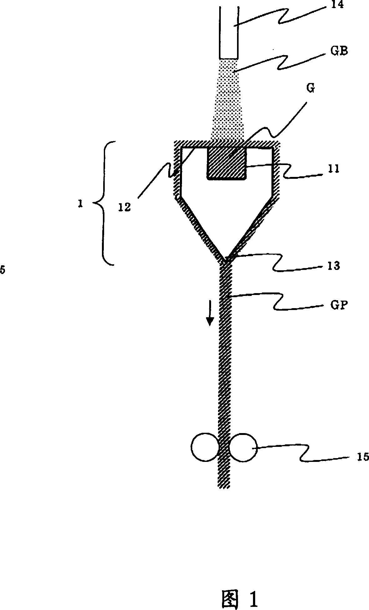
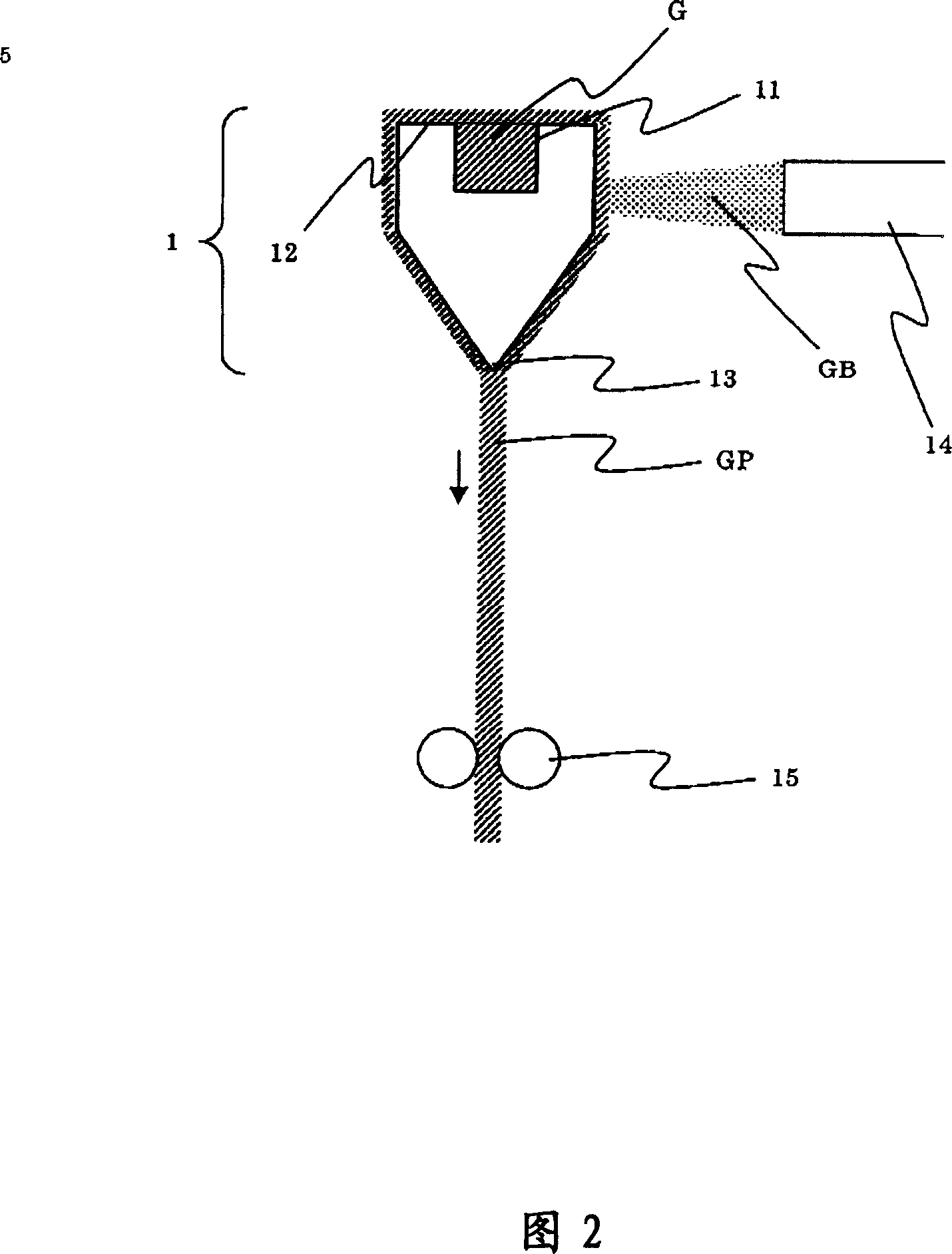
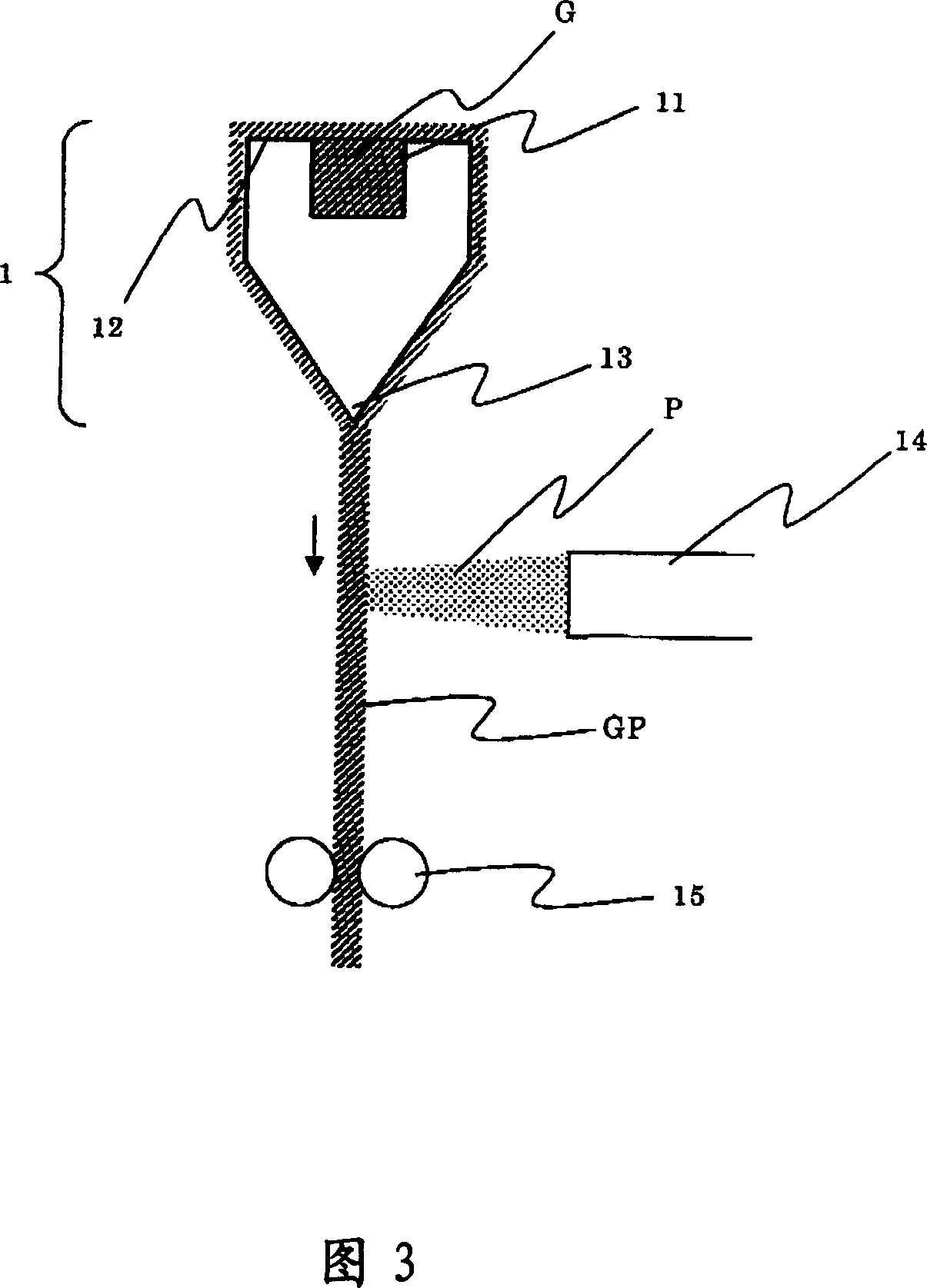

Image

  • Glass substrate and a manufacturing method thereof
  • Glass substrate and a manufacturing method thereof
  • Glass substrate and a manufacturing method thereof

Examples


Embodiment Construction

[0055] In order to further explain the technical means and effects of the present invention to achieve the intended purpose of the invention, the specific implementation, structure, characteristics and methods of the glass substrate and its manufacturing method proposed according to the present invention will be described below in conjunction with the accompanying drawings and preferred embodiments. Its effect is described in detail below.

[0056]

[0057] Fig. 1 shows a schematic configuration diagram of a glass manufacturing method according to a first embodiment. In FIG. 1 , 1 represents a fusion pipe, and this fusion pipe 1 has a groove-shaped portion 11 opened at the top, and bank-shaped portions 12 are arranged on both sides thereof. A blade-like portion 13 is provided at the lower end. A heater (not shown) is incorporated inside the melting tube 1, and the melting tube 1 is heated by the heater to keep the surface of the melting tube at a temperature at which the gl...


PUM

PropertyMeasurementUnit
heightaaaaaaaaaa
heightaaaaaaaaaa
thicknessaaaaaaaaaa

Abstract

The present invention provides a glass substrate which enables to manufacture a FPD in keeping cost low and in efficient, and to provide an efficient manufacturing method of a glass substrate. The method for manufacturing a glass substrate by fusion process comprising the following steps; flowing fused glass into a fusion pipe, and gradually cooling and solidifying the fused glass by flowing downward from the fusion pipe, wherein forming an asperity on a surface of the glass substrate by fastening and pressing the glass toward a direction of thickness of the glass with a pair of transfer rollers during the glass is flowing down from the fusion pipe.

Description

technical field [0001] The present invention relates to a glass substrate used in a flat panel display device (FPD) such as a liquid crystal panel, and a manufacturing method thereof, and more particularly to a glass substrate for a large FPD such as a television or a computer monitor. Background technique [0002] In recent years, the popularity of FPDs such as liquid crystal and plasma methods has been extremely fast, especially recently, a new generation of FPD field emission displays (Field Emission Display) has been launched, which has prompted related research and development to become more popular. [0003] In order to manufacture these FPDs, it is necessary to form a high-precision fine pattern on the surface of a flat glass substrate. Take a TFT liquid crystal element as an example for illustration. In a TFT liquid crystal element, a large number of thin film transistors (TFTs) are precisely arranged on the surface of a glass substrate so as to correspond to each p...

Claims


Application Information

Patent Timeline
Patent Type & Authority Applications(China)
IPC IPC(8): C03B17/06C03B13/06
CPCC03B17/064C03B17/068C03B17/065G02F1/13
Inventor 木村幸泰新田祐平
Owner NIKON CORP
Why Eureka
Try Eureka