Supercharge Your Innovation With Domain-Expert AI Agents!

Plasma display apparatus

A technology for plasma display panels and display devices, which is applied to identification devices, static indicators, cathode ray tube indicators, etc., can solve problems such as tremors, and achieve the effects of stable driving, shortening the required time, and preventing false discharges.

Inactive Publication Date: 2007-05-30
LG ELECTRONICS(NANJING) PLASMA CO LTD
View PDF0 Cites 0 Cited by
  • Summary
  • Abstract
  • Description
  • Claims
  • Application Information

AI Technical Summary

Problems solved by technology

That is, it is necessary to overcome problems such as the jitter phenomenon that occurs when the addressing discharge lags when the addressing pulse is applied.

Method used


Image

  • Plasma display apparatus
  • Plasma display apparatus
  • Plasma display apparatus

Examples


Embodiment Construction

[0062] Hereinafter, an introduction will be made with reference to pictures attached with specific examples of the present invention.

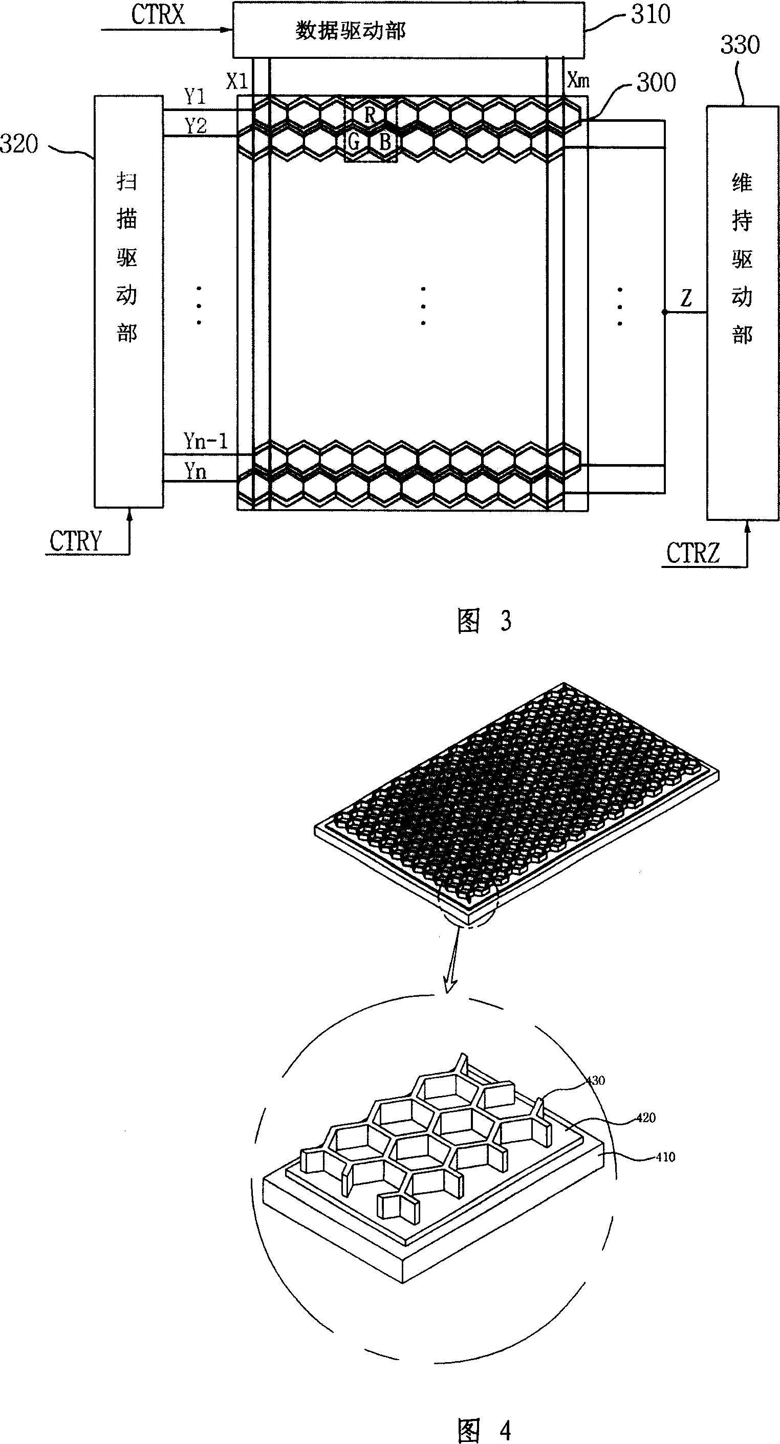
[0063] FIG. 3 is a diagram illustrating a plasma display device of an example of the present invention.

[0064] As shown in FIG. 3 , a plasma display device according to an example of the present invention includes a plasma display panel 300 , a data drive unit 310 , a scan drive unit 320 , and a sustain drive unit 330 .

[0065] The plasma display panel 300 is a front substrate (not shown in the figure) and a rear substrate (not shown in the figure) bonded together. Scan electrodes (Y1 to Yn) and sustain electrodes Z are formed on the front substrate, and a plurality of address electrodes (X1 to Xm) intersecting the scan electrodes (Y1 to Yn) and sustain electrodes Z are formed on the rear substrate.

[0066] Wherein, when the intersections of the scan electrodes (Y1 to Yn) and the address electrodes (X1 to Xm) form unit sub-pixels, R (Red)...


PUM

PropertyMeasurementUnit
Lengthaaaaaaaaaa

Abstract

The invention is an invention directed to a plasma display apparatus, more particular, a related invention of a plasma display apparatus capable of driving a high-definition plasma display panel with high speed. The plasma display apparatus of the invention is characterised by including a scanning electrode and a sustaining electrode; a plasma display panel in which each junction of an addressing electrode formed crossing with the scanning electrode forms each R, G, B sub-pixel, and the R, G, B sub-pixels are configured in a polygon; and a sustaining and driving unit which applies a first waveform on the sustaining electrode from a memory period of a resetting period to a period before applying a first scanning waveform on the scanning electrode, and applies a second waveform with a higher votlage level higher than the first waveform after applying the first waveform.

Description

technical field [0001] The present invention is an invention related to a plasma display device, more specifically, an invention related to a plasma display device capable of driving a high-definition plasma display panel at high speed. Background technique [0002] Generally, a plasma display device (Plasma Display Apparatus) includes a plasma display panel in which sub-pixels (Sub-Pixels) are formed by barrier ribs formed between a front substrate and a rear substrate. Each sub-pixel is filled with neon (Ne), helium (He) or an inert gas containing a mixed gas of neon and helium (Ne+He) and a small amount of xenon (Xe). When the high-frequency voltage is discharged, the inert gas generates vacuum ultraviolet rays (Vacuum Ultraviolet rays), which makes the phosphors formed between the barrier ribs emit light, thereby displaying images. Since such a plasma display panel can have a thin and light structure, it is attracting attention as a second-generation display device. ...

Claims


Application Information

Patent Timeline
IPC IPC(8): G09G3/28G09G3/20G09G5/02H01J17/49G09F9/313G09G3/291G09G3/296
CPCG09G3/2074G09G3/296G09G2300/0452G09G2310/0216G09G2310/0254G09G2320/0252H01J11/36
Inventor 朴記洛裵鐘運柳聖煥趙允珠黃斗勇
Owner LG ELECTRONICS(NANJING) PLASMA CO LTD
Features
  • R&D
  • Intellectual Property
  • Life Sciences
  • Materials
  • Tech Scout
  • Unparalleled Data Quality
  • Higher Quality Content
  • 60% Fewer Hallucinations
Learn More