
Control method of wireless link layer flow

A wireless link layer and flow control technology, applied in the field of communication, can solve problems such as low transmission efficiency and unusable flow control schemes, and achieve the effects of reducing impact, avoiding memory exhaustion, and improving link quality

Active Publication Date: 2007-05-30
DATANG MOBILE COMM EQUIP CO LTD
View PDF0 Cites 25 Cited by
  • Summary
  • Abstract
  • Description
  • Claims
  • Application Information

AI Technical Summary

Problems solved by technology

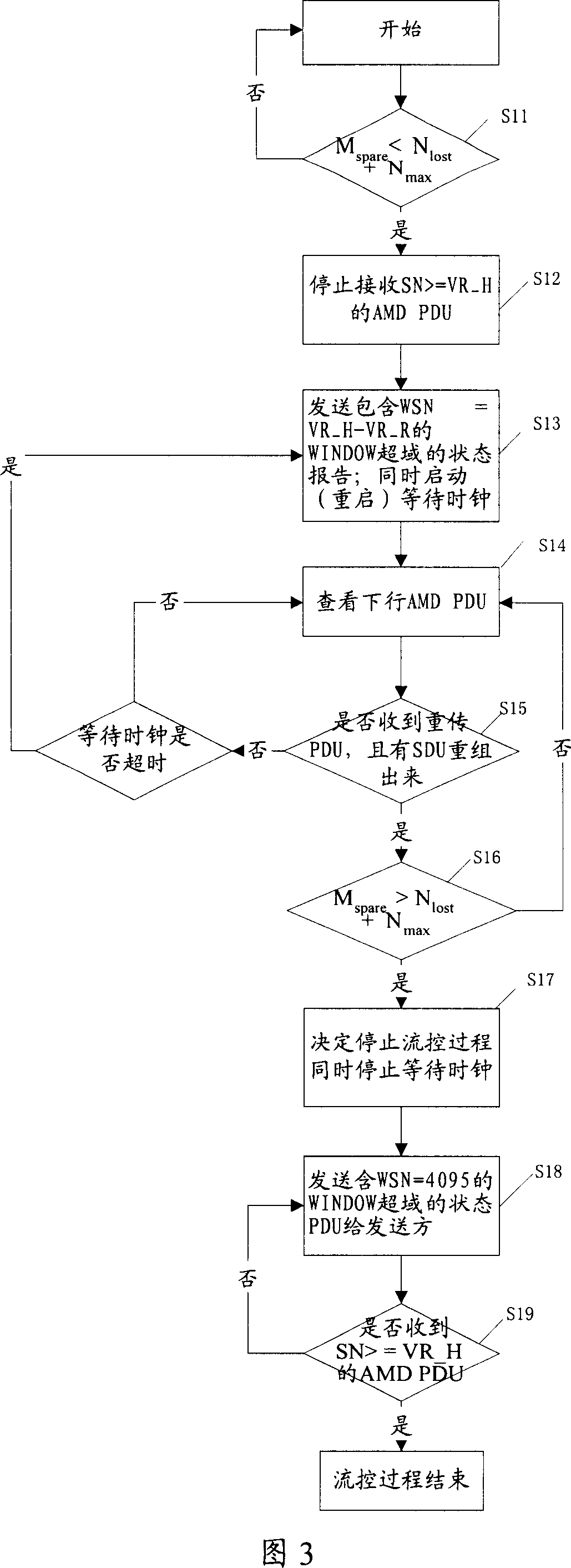
[0009] In addition, although the sending window in the 3GPP RLC protocol also uses the confirmation-sliding mechanism, in order to avoid the problem of low sending efficiency caused by the stagnation of the sending window in GPRS RLC, in 3GPP RLC, the sending window is generally set larger (the receiving window 2, 3 times), so the sending window rarely stagnates, and the flow control scheme of GPRS RLC cannot be used in 3GPP RLC
[0010] That is to say, there is currently no flow control scheme suitable for the link characteristics of 3GPP RLC, so that the 3GPP communication system can reasonably and efficiently perform flow control on the wireless link

Method used


Image

  • Control method of wireless link layer flow
  • Control method of wireless link layer flow
  • Control method of wireless link layer flow

Examples


Embodiment Construction

[0028] The present invention will be described in detail below in conjunction with the accompanying drawings.

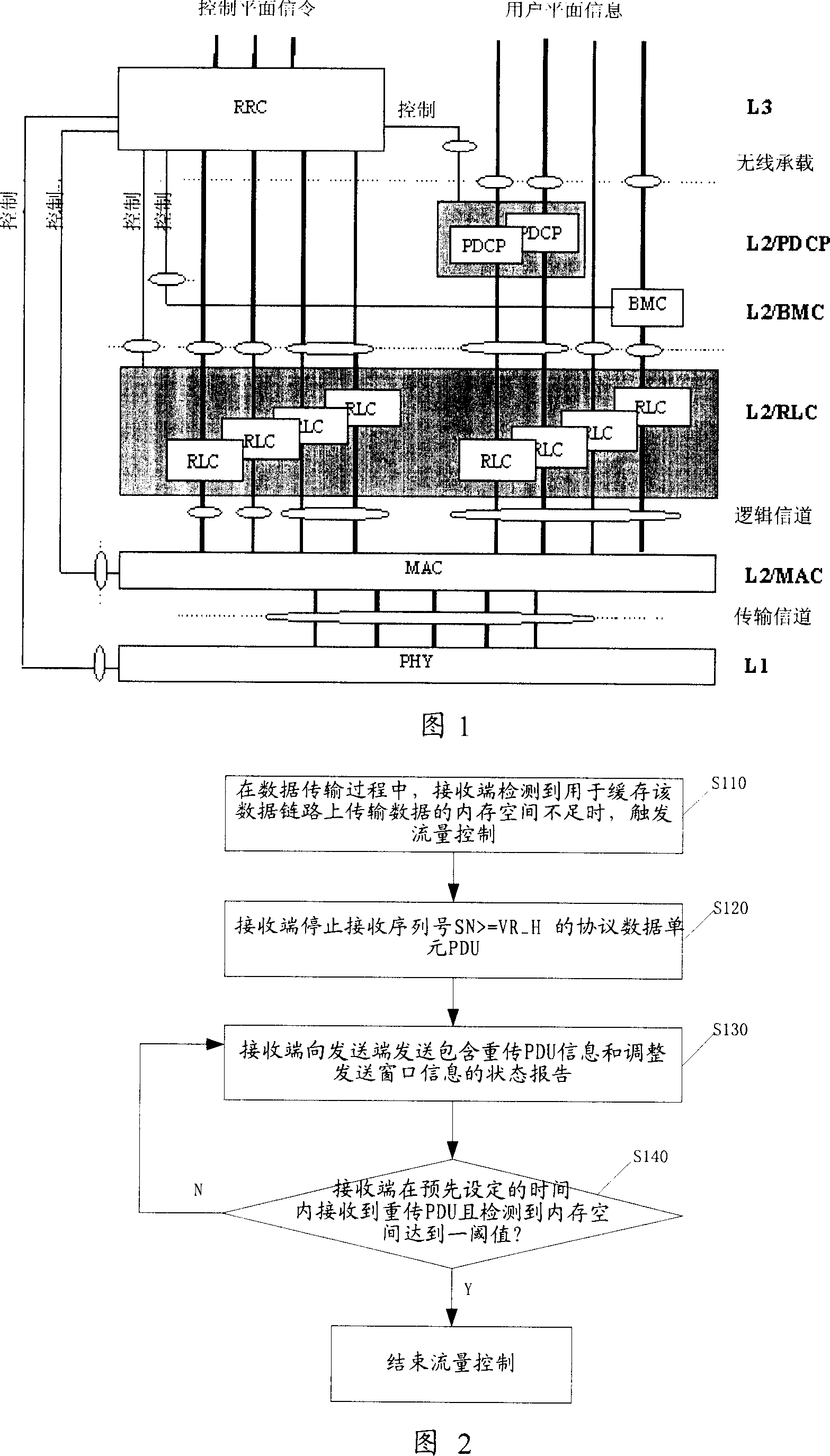
[0029] Please refer to FIG. 2 , which is a flow chart of the first wireless link layer flow control method disclosed in the present invention. It includes the following steps:

[0030] S110: During the data transmission process, when the receiving end detects that the memory space for caching the data transmitted on the data link is insufficient, flow control is triggered.

[0031] Due to cost and size constraints, the memory of the terminal will not be too large. If the RLC of the terminal establishes many logical paths at the same time, there may be a certain number of packet loss due to poor link quality. In this way, the terminal needs to cache a lot of PDUs, resulting in insufficient memory space for caching PDUs. Flow control is required.

[0032]The receiving end detects whether the memory space for buffering the transmission data on the data link is suffic...


PUM


Abstract

This invention relates to wireless linkage layer flow control method, which comprises the following steps: a, in data transmission process, receive end tests memory space for data transmission data and triggers flow control end; b, receive end stops receiving sequence SN>=VR-H agreement unit AMD PDU; c, receive end sends repeat PDU information and adjusts send window information status report; d, if the receive end receives the repeat PDU within reset time and tests memory data linkage transmission data to certain valve value then stops flow control, otherwise for step c.

Description

technical field [0001] The invention relates to the field of communication, in particular to a flow control method of RLC (Radio Link Layer) of 3GPP (Third Generation Mobile Communication System). Background technique [0002] In the existing TDD / CDMA mobile communication system, the architecture of the air interface protocol as shown in FIG. 1 is usually adopted. The air interface protocol system is mainly divided into three layers, the lowest layer is the physical layer (PHY) L1; above the physical layer is the data link layer L2, which includes the media access control layer (MAC) and the radio link control layer (RLC). [0003] RLC provides data link establishment and release services. On the control plane, RLC bears the upper layer services called Signal radio bearer (Signal radio bearer, SRB), and the data transmitted on the SRB is signaling; on the user plane, if PDCP (Packet Data Protocol Convergence Sublayer ) and BMC (broadcast / multicast control sublayer) are no...

Claims


Application Information

Patent Timeline
IPC IPC(8): H04L29/06H04L1/18
Inventor 邓伟许芳丽牟建斌
Owner DATANG MOBILE COMM EQUIP CO LTD
Learn More